Automatic solar silicon wafer cutting machine

A technology for solar silicon wafers and cutting machines, used in laser welding equipment, climate sustainability, manufacturing tools, etc., can solve the problems of affecting cutting accuracy, large vibration amplitude, and low cutting quality, and improve practicability and reliability. , improve practicality and practicality, improve the effect of practicality

Active Publication Date: 2021-02-09
DALIAN SANDAAOKE CHEM
View PDF10 Cites 0 Cited by
  • Summary
  • Abstract
  • Description
  • Claims
  • Application Information

AI Technical Summary

Problems solved by technology

[0002] As we all know, solar silicon wafers are mainly the basic components of solar panels, which play a major role in the conversion of solar energy into electrical energy by solar panels. Solar silicon wafers usually need to be cut into specified sizes during production to facilitate installation. The current cutting method of solar silicon wafers is mainly through wire cutting machine. When using this equipment, the flatness of the cutting surface of silicon wafers is poor, and the cutting quality is low. The vibration amplitude is relatively large, and the vibration is easily transmitted to the silicon wafer and affects its cutting accuracy

Method used


Image

  • Automatic solar silicon wafer cutting machine
  • Automatic solar silicon wafer cutting machine
  • Automatic solar silicon wafer cutting machine

Examples


Embodiment Construction

[0023] The specific implementation manners of the present invention will be further described in detail below in conjunction with the accompanying drawings and embodiments. The following examples are used to illustrate the present invention, but are not intended to limit the scope of the present invention.

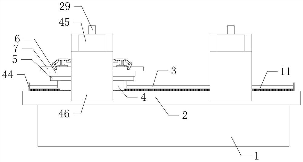
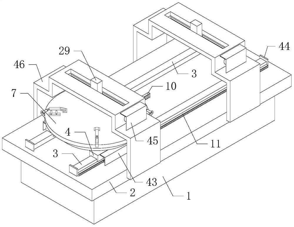
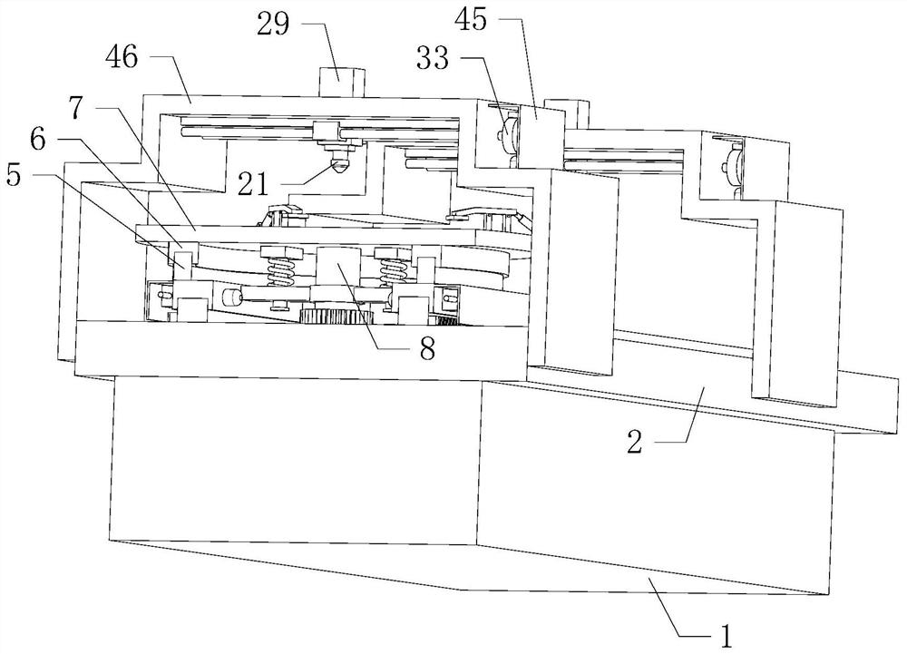
[0024] Such as Figure 1 to Figure 9 As shown, the solar silicon wafer automatic cutting machine of the present invention, when it is working, the working mode of the power device is to open the first motor 20, and the first motor 20 can drive the double output shaft speed reducer 19 to run, and the double output shaft speed reducer 19 Drive two groups of second bevel gears 16 to rotate through two groups of second rotating shafts 17, multiple groups of second fixing frames 18 can support two groups of second rotating shafts 17, two groups of second bevel gears 16 are connected with two groups of first bevel gears respectively Gears 15 mesh, two groups of second bevel gea...


PUM


Abstract

The invention relates to the technical field of mechanical equipment, in particular to an automatic solar silicon wafer cutting machine which can effectively improve the flatness of the section of a silicon wafer and improve the cutting quality by automatically cutting the silicon wafer, and meanwhile, the silicon wafer is subjected to one-way cutting treatment by adopting laser, so that the stability of the equipment during operation can be effectively improved, the stability of the silicon wafer is improved, the influence of equipment vibration on silicon wafer cutting work is reduced, the cutting precision is improved, and the practicability and reliability are improved; and the automatic solar silicon wafer cutting machine comprises a base, a workbench, two groups of first linear guiderails, two groups of first sliding blocks, an annular guide rail and an annular sliding groove, the workbench is installed on the base, the two groups of first linear guide rails are transversely installed on the front side and the rear side of the top of the workbench correspondingly, and the two groups of first sliding blocks are slidably installed on the two groups of first linear guide railscorrespondingly.

Description

technical field [0001] The invention relates to the technical field of mechanical equipment, in particular to an automatic solar silicon wafer cutting machine. Background technique [0002] As we all know, solar silicon wafers are mainly the basic components of solar panels, which play a major role in the conversion of solar energy into electrical energy by solar panels. Solar silicon wafers usually need to be cut into specified sizes during production to facilitate installation. The current cutting method of solar silicon wafers is mainly through wire cutting machine. When using this equipment, the flatness of the cutting surface of silicon wafers is poor, and the cutting quality is low. The vibration amplitude is relatively large, and the vibration is easily transmitted to the silicon wafer and affects its cutting accuracy. Contents of the invention [0003] In order to solve the above technical problems, the present invention provides an automatic cutting process for s...

Claims


Application Information

Patent Timeline
Patent Type & Authority Applications(China)
IPC IPC(8): B23K26/38B23K26/402B23K26/70
CPCB23K26/38B23K26/402B23K26/702Y02P70/50
Inventor 吴禹凡高洪庆
Owner DALIAN SANDAAOKE CHEM
Why Eureka
Try Eureka