Spindle unit

A spindle and outer peripheral surface technology, applied in the field of spindle units, can solve problems such as reduced productivity and time-consuming

Pending Publication Date: 2021-02-09
DISCO CORP
View PDF3 Cites 0 Cited by
  • Summary
  • Abstract
  • Description
  • Claims
  • Application Information

AI Technical Summary

Problems solved by technology

However, in order to carry out such cleaning, it is necessary to disassemble the cover, clean it, and install the cover, which takes time and reduces productivity.

Method used


Image

  • Spindle unit
  • Spindle unit
  • Spindle unit

Examples


Embodiment Construction

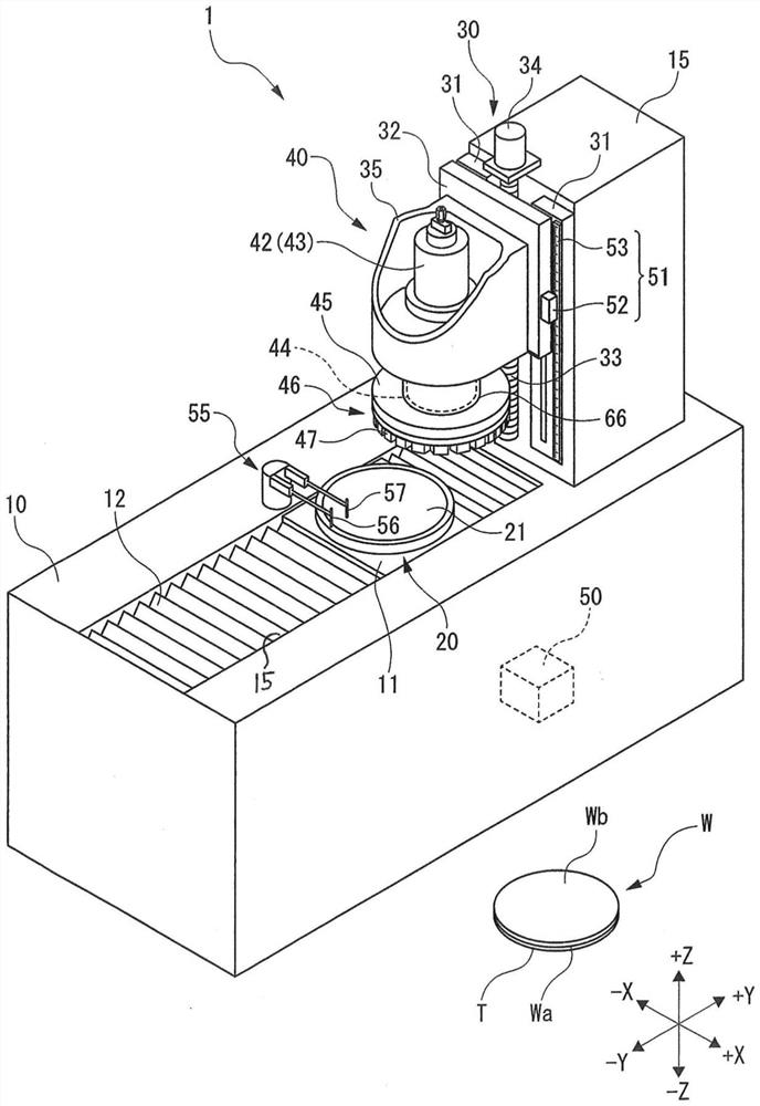
[0022] figure 1 The shown grinding apparatus 1 is an apparatus for performing grinding processing on a wafer W as a workpiece. figure 1 The wafer W shown is, for example, a circular semiconductor wafer. A plurality of devices (not shown) are formed on the front surface Wa of the wafer W. As shown in FIG. Wa on the front figure 1 The center faces downward and is protected by affixing a protective tape T. The back surface Wb of the wafer W is a surface to be processed which is subjected to grinding.

[0023] The grinding apparatus 1 has a base 10 extending in the Y-axis direction, and a column 15 erected on the +Y direction side of the base 10 . A rectangular opening 15 extending in the Y-axis direction is formed on the upper surface of the base 10 . This opening 15 is covered by a moving plate 11 and a corrugated waterproof cover 12 .

[0024] A chuck table 20 is disposed so as to penetrate through the moving plate 11 . The chuck table 20 is a disk-shaped table for holdi...


PUM


Abstract

The invention provides a spindle unit which suppresses difficult rotation of a spindle because of machining debris. A sealing portion (68) on a lower end of a cover portion (67) of a spindle cover (66) has an upper side surface (68a) and a lower side surface (68b) that are inclined toward an outer circumferential surface (77a) of the spindle (44). A larger-diameter disk and the outer circumferential surface (77a) of the spindle (44) define therebetween a second gap (T2) that is narrower than a first gap (T1) defined between the spindle (44) and the cover portion (67). The second gap is effective to prevent a processing waste liquid from entering between the spindle (44) and the spindle cover (66) to prevent a solid waste contained in the processing waste liquid from sticking to the spindle. The spindle (44) is thus prevented from becoming less liable to rotate smoothly due to solid waste deposits.

Description

technical field [0001] The invention relates to a spindle unit. Background technique [0002] In the grinding device, the workpiece held by the chuck table is ground by the grinding wheel while supplying grinding water. The grinding tool is ring-shaped arranged on the abutment, and forms a grinding wheel together with the abutment. The grinding wheel is mounted on the mounting seat of the spindle unit and rotates at high speed. [0003] The spindle unit has: a spindle; a mounting seat connected to the lower end of the spindle; a housing that supports the side of the spindle with an air bearing; and a motor that rotates the spindle. [0004] When a workpiece is ground, waste grinding fluid containing machining waste such as grinding dust is generated. In order to prevent the grinding waste liquid from adhering to the side of the main shaft, a cover is provided to cover the side of the main shaft. The cover is disposed between the lower end of the housing and the upper sur...

Claims


Application Information

Patent Timeline
Patent Type & Authority Applications(China)
IPC IPC(8): B24B19/00B24B41/00B24B41/02B24B41/04B24B41/06B24B47/20B24B49/00B24B55/03B24B55/04
CPCB24B19/00B24B41/02B24B41/04B24B41/06B24B55/04B24B47/20B24B41/005B24B49/00B24B55/03B24B55/02B24B55/00H01L21/67092B23Q11/0883B23Q11/127B23Q1/70F16C32/06
Inventor 刘乃力
Owner DISCO CORP
Why Eureka
Try Eureka