Collaborative management method suitable for fuel cell vehicle thermal system

A fuel cell and collaborative management technology, applied in the direction of fuel cell heat exchange, fuel cell, fuel cell additives, etc., can solve the problems of detrimental power battery life, fuel cell situation, fuel cell and power battery cold start, etc. Achieve the effect of improving work performance and promoting high efficiency

Pending Publication Date: 2021-02-09
ZHEJIANG UNIV
View PDF0 Cites 4 Cited by
  • Summary
  • Abstract
  • Description
  • Claims
  • Application Information

AI Technical Summary

Problems solved by technology

[0005] 1. Most of the existing technologies have relatively limited effect on efficient thermal management of fuel cells alone, and there is no coordinated efficient management method
[0006] 2. When a fuel cell vehicle works in a low temperature environment, it will face the problem of cold start of the fuel cell and power battery
If the PTC heater is used to consume battery power to heat the cooling water circuit of the fuel cell and power battery during cold start, it will increase the overall energy consumption of the system and damage the service life of the power battery
[0007] 3. Most of the existing technologies only recover and utilize waste heat from the heat produced by fuel cells, while ignoring the efficient utilization of waste heat from main heat-producing components such as power batteries, motor electrical systems, and air compressors
[0008] 4. In the prior art, there is a lack of methods for efficiently utilizing waste heat to cool the passenger compartment

Method used


Image

  • Collaborative management method suitable for fuel cell vehicle thermal system
  • Collaborative management method suitable for fuel cell vehicle thermal system
  • Collaborative management method suitable for fuel cell vehicle thermal system

Examples


Embodiment Construction

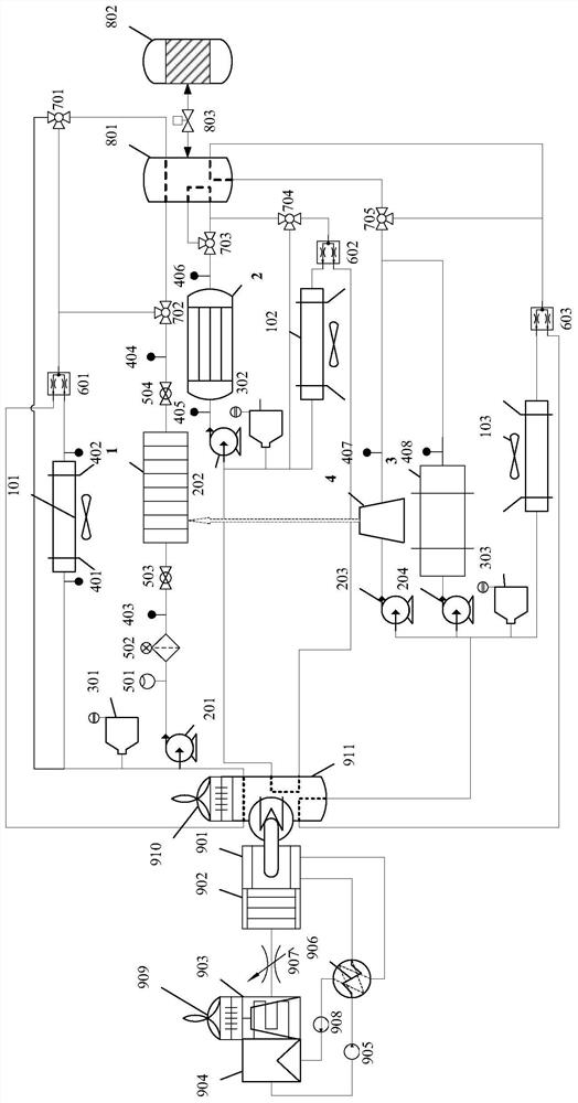
[0049] In order to make the object, technical solution and advantages of the present invention clearer, the present invention will be further described in detail below in conjunction with the accompanying drawings and embodiments. In order to make the drawings more concise and intuitive, each figure only schematically shows the parts related to the present invention, omitting some system structures that are not very relevant to the present invention, and they do not represent the complete structure of the present invention. It should be understood that the specific embodiments described here are only used to explain the present invention, not to limit the present invention.

[0050] In the description of the present invention, it should be noted that the specific types and models of each component are only preferred embodiments of the present invention, and those of ordinary skill in the art can choose other Different types of components achieve the same effect and obtain othe...


PUM


Abstract

The invention discloses a collaborative management method suitable for a fuel cell automobile thermal system. The fuel cell automobile thermal system comprises a fuel cell heat dissipation loop, a power cell heat dissipation loop, a heat dissipation loop used for motor electricity and an air compressor, a thermochemical heat storage module and an adsorption type refrigeration module. All the loopsare cooperatively managed, heat generated by all the components can be efficiently stored while the heat dissipation requirements of all the components are met, and waste heat can be directly used for supplying heat to a passenger compartment or supplying cold air through the adsorption type refrigeration technology. A chemical heat storage technology is further adopted, heat energy can be storedfor a long time with almost no heat loss, and the stored heat can be used for passenger compartment heating when a vehicle is started and cold start heating of a fuel cell and a power cell in a low-temperature environment. The working performance and reliability of core components of the fuel cell vehicle can be remarkably improved, and high efficiency, safety and energy conservation of the fuelcell vehicle are promoted.

Description

technical field [0001] The invention belongs to the technical field of fuel cell vehicles and relates to a collaborative management method suitable for the thermal system of fuel cell vehicles. Background technique [0002] Fuel cell is considered to be the most promising new energy power system, and its research and development technology has been continuously upgraded, and it has become one of the competition focuses of the world's major automobile manufacturers. As an ideal alternative to traditional vehicles, fuel cell vehicles have inherent advantages such as clean and non-polluting, quiet and noise-free, stable power output and convenient fuel replenishment, but there are still problems such as high cost, immature hydrogen storage technology, and inadequate construction of auxiliary facilities. Improvement and low efficiency of thermal system management. [0003] At present, some fuel cell commercial vehicle models in China have achieved mass production and are the fi...

Claims


Application Information

Patent Timeline
Patent Type & Authority Applications(China)
IPC IPC(8): B60L58/26B60L58/33B60L58/40B60H1/14B60H1/32H01M8/04007H01M8/04029H01M10/613H01M10/615H01M10/625H01M10/6567H01M10/663H01M10/667
CPCB60H1/143B60L2240/545B60L58/26B60L58/33B60L58/40B60H1/32014H01M8/04029H01M8/04052H01M10/613H01M10/615H01M10/625H01M10/6567H01M10/663H01M10/667Y02E60/10Y02E60/50Y02T10/70Y02T10/88Y02T90/40
Inventor 翁昕晨黄瑞俞小莉陈俊玄祝庆伟陈沛禹
Owner ZHEJIANG UNIV
Why Eureka
Try Eureka