
Gravity-driven spatial resolution powder atomic layer deposition equipment, method and application

An atomic layer deposition, powder technology, applied in the coating, metal material coating process, gaseous chemical plating and other directions, can solve the problems of increasing the coating cost, reducing the film coverage, sample agglomeration, etc., to improve the coating efficiency, The effect of high film growth efficiency and low coating cost

Active Publication Date: 2021-02-09
NANKAI UNIV
View PDF5 Cites 1 Cited by
  • Summary
  • Abstract
  • Description
  • Claims
  • Application Information

AI Technical Summary

Problems solved by technology

[0004] (1) The existing technology cannot avoid opening the cavity to inject samples, which wastes time and increases the cost of coating
[0005] (2) When increasing the efficiency in the prior art, it is necessary to increase the cavity volume and increase the purge time
[0006] (3) Sample agglomeration is prone to occur in the prior art, resulting in reduced film coverage
[0007] The difficulty of solving the above problems and defects is: how to improve the growth efficiency of the film in the existing technology; it is impossible to avoid the steps of cooling down, opening the cavity, taking out the sample, and putting in the sample to cause a lot of time waste

Method used


Image

  • Gravity-driven spatial resolution powder atomic layer deposition equipment, method and application
  • Gravity-driven spatial resolution powder atomic layer deposition equipment, method and application
  • Gravity-driven spatial resolution powder atomic layer deposition equipment, method and application

Examples


Embodiment Construction

[0050] In order to make the object, technical solution and advantages of the present invention more clear, the present invention will be further described in detail below in conjunction with the examples. It should be understood that the specific embodiments described here are only used to explain the present invention, not to limit the present invention.

[0051] Aiming at the problems existing in the prior art, the present invention provides a gravity-driven spatial resolution powder atomic layer deposition equipment, method and application. The present invention will be described in detail below with reference to the accompanying drawings.

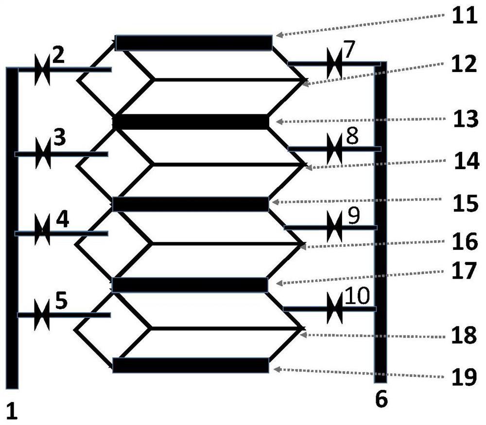
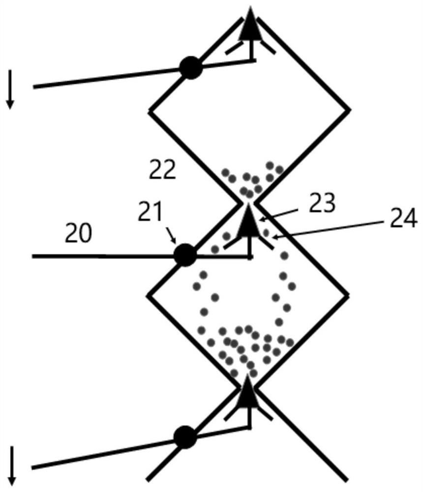
[0052] The powder atomic layer deposition equipment of the present invention is provided with a heatable main chamber; a movable sealing structure is arranged between the multi-stage heatable main chambers, and is sealed by rubber-metal / rubber; each stage of the heatable main chamber Both ends are fixed with a heatable gas pipeline, and...


PUM


Abstract

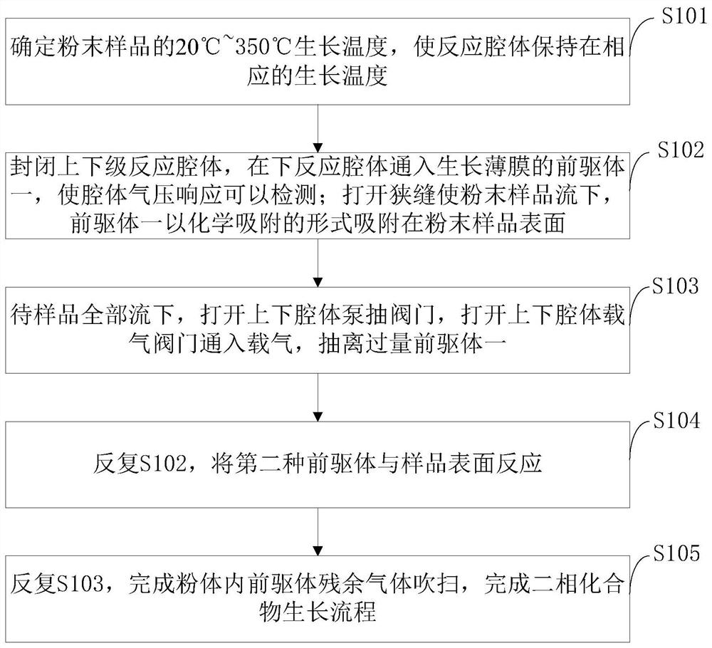
The invention belongs to the technical field of atomic layer deposition and discloses gravity-driven spatial resolution powder atomic layer deposition equipment, a gravity-driven spatial resolution powder atomic layer deposition method and application. The powder atomic layer deposition equipment is provided with heatable main chambers; movable sealing structures are arranged between the multiplestages of heatable main chambers, and the heatable main chambers are sealed through rubber-metal / rubber; heatable gas pipelines are fixed to the two ends of each stage of heatable main chamber, and powder filters are arranged at the joints of the heatable gas pipelines; one end of each stage of heatable main chamber is connected with a precursor and carrier gas through the corresponding heatable gas pipeline, and opening and closing are controlled via an electromagnetic valve; the other end of each stage of heatable main chamber is connected with a vacuum pump through the corresponding heatable gas pipeline, opening and closing are controlled via an electromagnetic or pneumatic valve, and residual gas analyzers or vacuum gauges can be arranged at the two ends of the valve; and the whole equipment can be provided with a vibrator. According to the gravity-driven spatial resolution powder atomic layer deposition equipment, the gravity-driven spatial resolution powder atomic layer deposition method and application, a chamber body is designed in a continuous growth mode, the coating efficiency is obviously improved, and the powder coating cost is reduced.

Description

technical field [0001] The invention belongs to the technical field of atomic layer deposition, and in particular relates to a gravity-driven space resolution powder atomic layer deposition equipment, method and application. Background technique [0002] At present, electrode materials in energy fields such as lithium batteries and hydrogen energy batteries are usually powders. A large number of literatures have reported that the surface coating modification of powder electrode materials by ALD can delay the appearance of dendrites and prolong the service life of batteries. A large number of laboratory-level powder surface coating technologies have been reported, but in principle, it is still immature for large-scale industrial production, because powder samples are usually easy to agglomerate, and the pressure of the precursor is not high. Even through traditional fluidized bed and other solutions, it is difficult to achieve High coverage. For the existing fluidized bed po...

Claims


Application Information

Patent Timeline
IPC IPC(8): C23C16/455C23C16/54C23C16/34
CPCC23C16/34C23C16/4417C23C16/45544C23C16/54
Inventor 董红冯泽
Owner NANKAI UNIV
Learn More