Dynamic vision sensor and laser radar data fusion method

A visual sensor and lidar technology, applied in instrumentation, surveying and navigation, photogrammetry/video surveying, etc., can solve the problems of not reaching pixel-level accuracy, large amount of calculation, etc., to reduce the amount of calculation and improve the accuracy , avoid the effect of influence

Active Publication Date: 2021-02-09
SUN YAT SEN UNIV
View PDF11 Cites 15 Cited by
  • Summary
  • Abstract
  • Description
  • Claims
  • Application Information

AI Technical Summary

Problems solved by technology

This scheme can improve the effect of target detection, but it adopts the method of clustering the data separately and then registering them. The obtained common areas are fused data, and the calculation amount is relatively large, and the pixel-level accuracy is not achieved.

Method used


Image

  • Dynamic vision sensor and laser radar data fusion method
  • Dynamic vision sensor and laser radar data fusion method
  • Dynamic vision sensor and laser radar data fusion method

Examples


Embodiment

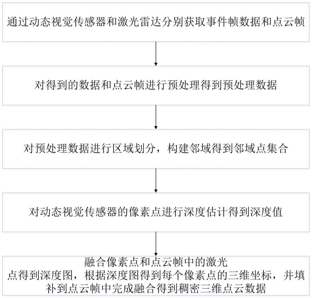
[0063] Such as figure 1 Shown is the embodiment of the method for fusion of dynamic visual sensor and laser radar data of the present invention, comprising the following steps:

[0064] S1: Obtain event frame data and point cloud frames through dynamic visual sensors and lidar respectively;

[0065] S2: Preprocessing the obtained data and point cloud frames to obtain preprocessed data;

[0066] S3: Divide the preprocessed data into regions, construct neighborhoods to obtain a set of neighborhood points;

[0067] S4: Perform depth estimation on the pixels of the dynamic vision sensor to obtain a depth value;

[0068] S5: Fusion pixel points and points in the point cloud frame to obtain a depth map, obtain the three-dimensional coordinates of each pixel point according to the depth map, and fill it into the point cloud frame to complete the fusion to obtain dense three-dimensional point cloud data.

[0069] The data produced by dynamic vision sensors is a stream of events. A...


PUM


Abstract

The invention relates to the technical field of machine vision, in particular to a dynamic vision sensor and laser radar data fusion method which comprises the following steps of S1, respectively obtaining event frame data and a point cloud frame through a dynamic vision sensor and a laser radar; s2, preprocessing the obtained data and point cloud frames to obtain preprocessed data; s3, performingregion division on the preprocessed data, and constructing neighborhoods to obtain a neighborhood point set; s4, performing depth estimation on pixel points of the dynamic vision sensor to obtain a depth value; and S5, fusing the pixel points and points in the point cloud frame to obtain a depth map, obtaining three-dimensional coordinates of each pixel point according to the depth map, and filling the three-dimensional coordinates into the point cloud frame to complete fusion to obtain dense three-dimensional point cloud data. According to the method, the dynamic vision sensor is used for outputting data streams, dense event points can be obtained and fused with the point cloud data of the laser radar to form dense point cloud data, and the accuracy of the algorithm is greatly improved.

Description

technical field [0001] The invention relates to the technical field of machine vision, and more specifically, to a method for fusing dynamic vision sensor and laser radar data. Background technique [0002] At present, commonly used sensor devices include cameras, lidar, dynamic vision sensors, etc. Does the camera output the image information of the environment in the form of fixed-frequency acquisition frames, which cannot collect position information and have high redundancy, high delay, high noise, and low dynamic range? and high data volume and other defects; lidar can generate point cloud data of the three-dimensional space form of the surrounding environment, but one of the important defects of the relatively low-priced three-dimensional lidar is low resolution; dynamic vision sensors only output pixels that change in light intensity Instead of passively reading out the information of each pixel in the "frame" sequentially, eliminating redundant data from the source, ...

Claims


Application Information

Patent Timeline
Patent Type & Authority Applications(China)
IPC IPC(8): G01S17/86G01S17/894G01C11/04G06K9/62
CPCG01S17/86G01S17/894G01C11/04G01C11/36G06F18/253Y02A90/10
Inventor 黄凯朱裕章李博洋孟浩宋日辉
Owner SUN YAT SEN UNIV
Why Eureka
Try Eureka