[0032]The present invention will be described in detail below in conjunction with specific embodiments. The following examples will help those skilled in the art to further understand the present invention, but do not limit the present invention in any form. It should be pointed out that for those of ordinary skill in the art, a number of modifications and improvements can be made without departing from the concept of the present invention. These all belong to the protection scope of the present invention.
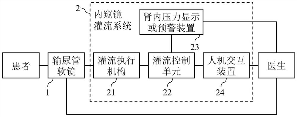
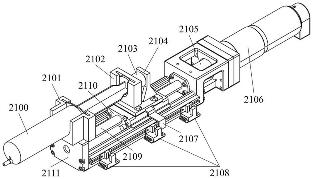
[0033]figure 1 It is a schematic diagram of the frame of an endoscope perfusion system according to an embodiment of the present invention. Referencefigure 1 As shown, in this embodiment, an endoscopic perfusion system 2 is provided. The system includes: a perfusion execution mechanism 21 and a perfusion control unit 22. Among them, the perfusion actuator 21 includes a liquid injection device and a force sensor 2103. The liquid injection device is used to complete liquid injection during surgery, and the force sensor 2103 is used to measure the force value during the liquid injection process of the liquid injection device; the perfusion control unit 22 The force value of the sensor 2103 is analyzed and calculated to obtain the intrarenal pressure value. At the same time, the perfusion control unit 22 receives external control instructions and controls the work of the perfusion actuator 21 through the control instructions.
[0034]When specifically used in surgery, the soft part of the flexible ureteroscope 1 is inserted into the patient's body, and the perfusion actuator 21 can be connected to the channel of the flexible ureteroscope 1 through an injection extension tube and a Y-valve or other connecting pipes to achieve perfusion. The liquid flows into the channel of the flexible ureteroscope 1. The perfusion execution mechanism 21 and the perfusion control unit 22 may be connected by means including but not limited to electrical connection, WiFi connection, and 5G connection. The perfusion execution mechanism 21 receives the control of the perfusion control unit 22, performs perfusion actions, and feeds back the force value to the perfusion control unit 22. The perfusion control unit 22 analyzes and calculates the force value to obtain the intrarenal pressure value.
[0035]The above-mentioned embodiments of the present invention can realize the non-contact intrarenal pressure monitoring function. Since it is not in contact with the human body, the safety is better, the disinfection and sterilization is more convenient, and it is beneficial to save costs and reduce the burden on hospitals and patients. It should be noted that the endoscopic perfusion system 2 can be used alone or together with other perfusion equipment.
[0036]In some embodiments of the present invention, the liquid injection device may adopt a syringe 2100, and the force sensor 2103 is fixedly connected to the piston core rod of the syringe 2100. The force sensor 2103 can measure the force value of the piston core rod in real time and provide the force value. Of course, other liquid injection devices other than the syringe 2100 can also be used in other embodiments, as long as the force sensor 2103 can measure the force value during the liquid injection process.
[0037]In order to better facilitate the operation of the user, on the basis of the above embodiments, the endoscopic perfusion system 2 may further include an intrarenal pressure display or early warning device 23 and/or a human-computer interaction device 24. The device 23 and the human-computer interaction device 24 are respectively connected to the perfusion control unit 22. The intra-renal pressure display or early warning device 23 is used to display the intra-renal pressure during operation. When the intra-renal pressure exceeds a preset value, an early warning is issued to remind the operator . The early warning method can adopt a variety of methods, such as voice broadcast early warning, buzzer early warning, sound and light early warning, etc. The human-computer interaction device 24 is used by the operator to control the work of the perfusion actuator 21 by operating the perfusion control unit 22. Specifically, the human-computer interaction device 24 may be a button switch, a foot switch, a touch screen or a microcomputer, etc. . The obtained intra-renal pressure information is fed back to the operator through the intra-renal pressure display or early warning device 23 to assist the operator in making decisions and achieve the control of the intra-renal pressure at a desired level. Of course, the perfusion control unit 22 can also receive control instructions through the human-computer interaction device 24, and automatically control the intra-renal pressure at a desired level through feedback control.
[0038]The connections between the intra-renal pressure display or early warning device 23, the human-computer interaction device 24, and the perfusion control unit 22 in the above embodiments can be wired or wireless, including but not limited to electrical connection, WiFi connection, and 5G connection. Wait. In some embodiments, the intra-renal pressure display or early warning device 23 and the human-computer interaction device 24 can also be combined into one, for example, a computer with a touch screen is used.
[0039]In some embodiments of the present invention, the perfusion control unit 22 includes: a receiving module and a processing module, wherein the receiving module receives the force value measured by the force sensor 2103; the processing module adopts a pre-established kidney according to the force value received by the receiving module. The corresponding relationship between the internal pressure and the force value measured by the force sensor is calculated to obtain the intra-renal pressure value. Among them, the corresponding relationship is a functional relationship related to variables such as perfusion speed and pipeline parameters. Specifically, in a preferred embodiment, it may be the following functional relationship:
[0040]
[0041]Where P is the pressure in the kidney, F is the force value measured by the force sensor, S is the inner diameter of the syringe 2100, v is the advancing speed of the plunger rod of the syringe 2100, k and f(v) are the parameters to be determined, which can be obtained through experimental calibration . The calibration method may be to use a standard pressure sensor to measure the intrarenal pressure value P in the model at a preset speed v, and at the same time to read the force value F measured by the force sensor, to fit the relationship between the two, and calculate the parameters to be determined.
[0042]Among them, the processing module can be implemented by hardware or software program. One or more methods such as physical model methods, experimental methods, and data-driven methods can be used to establish in advance the corresponding relationship between the intra-renal pressure and the force value measured by the force sensor. The processing module can be an intelligent terminal such as a computer or a microprocessor that can install the above program, or it can be a simple above-mentioned program combined with other parts, such as an intra-renal pressure display or early warning device 23 or a human-computer interaction device 24. .
[0043]It should be noted that in this embodiment, by pre-establishing the corresponding relationship between the intra-renal pressure and the value measured by the force sensor 2103, and applying the relationship to the perfusion control unit 22, the detection and early warning of the intra-renal pressure can be realized in real time. Of course, in other embodiments, other methods that can establish the above-mentioned correspondence relationship may also be adopted.
[0044]The above-mentioned embodiments realize the non-contact intrarenal pressure monitoring function without modifying any existing surgical instruments (ureteral sheaths and guide wires) that invade the human body, which further improves the applicability of the system.
[0045]Such asfigure 2As shown, it is a schematic diagram of a perfusion implementing mechanism 21 according to a preferred embodiment of the present invention. The perfusion actuator 21 may further include a base 2111, a linear motion device, and a power generating device on the basis of the foregoing embodiment. The linear motion device and the power generating device are respectively fixedly connected to the base 2111, and the barrel of the syringe 2100 is fixedly connected to In the base 2111, the piston core rod of the syringe 2100 is fixedly connected to the linear motion device, and the power generating device is used to provide power to the linear motion device. Wherein, the piston core rod of the syringe 2100 is arranged on the linear motion device, and is driven by the linear motion device to perform linear motion.
[0046]In some embodiments of the present invention, the linear motion device may be a screw slider, a crank slider mechanism, a timing belt, a rack and pinion, a single-axis robot or a linear actuator, etc., and the power generating device may be a motor, a pneumatic device, or Hydraulic equipment, etc. In the above embodiment, the base 2111, the linear motion device and the power generating device are designed and adjusted as required. The perfusion actuator 21 may also have other structures, as long as it can perform the same function as described above, and is not limited to the structure described above.
[0047]Specifically, in one embodiment, when the power generating device is a motor 2106 and the linear motion device is a screw slider, one end of the base 2111 is provided with a front fixing groove 2101, and the barrel of the syringe 2100 is arranged in the front fixing groove 2101 , The motor 2106 is fixedly connected to the other end of the base 2111, the middle of the base 2111 is provided with a matching slide rail and a sliding block 2110, the sliding block 2110 is fixedly connected with a connecting support 2104, and the connecting support 2104 is fixedly connected to the force sensor 2103, The force sensor 2103 is also fixedly connected to the push rod groove 2102, the piston core rod of the syringe 2100 is arranged in the push rod groove 2102, the screw rod 2109 passes through and is movably connected to the slider 2110, and the screw rod 2109 is connected to the motor through a coupling 2105 2106.
[0048]In some embodiments of the present invention, on the basis of the above-mentioned embodiments, the perfusion actuator 21 further includes a position sensing device. The position sensing device is fixed on the base 2111 to measure the movement position information of the linear motion device for realizing linear motion. Limit protection of the motion device, automatic origin search and reset function. Specifically, the position sensing device may be a photoelectric switch 2108, or a touch switch, or a distance sensor. For example, in one embodiment, when the photoelectric switch 2108 is used, it can be matched with the light-shielding plate 2107. There can be multiple photoelectric switches 2108. The multiple photoelectric switches 2108 are fixedly connected to the side of the base 2111 at intervals, and the light-shielding plate 2107 is fixedly connected. On the slider 2110 of the linear motion device. The photoelectric switch 2108 detects the position information of the linear motion device by shielding the light beam by the shading plate 2107, and transmits the motion position information of the linear motion device to the photoelectric switch 2108 to realize limit protection, automatic origin search and/or reset functions.
[0049]In the above embodiment, the base 2111 is used as the base of the perfusion actuator 21 to connect the front fixing groove 2101, the screw rod 2109, the motor 2106 and the photoelectric switch 2108, and provide a sliding rail for the slider 2110; the motor 2106 passes through the coupling 2105 is connected to the screw rod 2109; the screw rod 2109 is installed on the base 2111 through the bearing and the bearing seat; the slider 2110 is installed on the screw rod 2109 and the base 2111; the motor 2106 is converted into rotary motion through the coupling 2105 and the screw rod 2109 The linear motion is transmitted to the slider 2110. The light-shielding plate 2107 is installed on the slider 2110, and transmits the position information of the slider 2110 to the photoelectric switch 2108 to realize limit protection, automatic origin search and reset functions. The syringe of the syringe 2100 is placed in the front fixing groove 2101 to keep the syringe fixed during the perfusion process; the plunger rod of the syringe 2100 is placed in the push rod groove 2102, and the push rod groove 2102 is installed on one of the force sensors 2103 by bolts. On the end face, the other end face of the force sensor 2103 is connected to the connecting support 2104 through a bolt, and the connecting support 2104 is installed on the slider 2110 through a threaded connection to realize the piston core rod and the push rod groove 2102 of the syringe 2100, and the force sensor 2103 Together with the connecting support 2104, the slider 2110 moves linearly on the base 2111, and the force sensor 2103 can measure the force of the plunger rod of the syringe 2100 received by the push rod groove 2102 in real time, and transmit it to the perfusion control unit 22.
[0050]Of course, the above are only some of the embodiments of the present invention. In other embodiments, the linear motion device can be any one of a screw slider, a crank slider mechanism, a timing belt, a rack and pinion, a single-axis robot, or a linear actuator. The kind is not limited to the above-mentioned screw slider. At the same time, the power generating device may be any of a motor, a pneumatic device or a hydraulic device, and is not limited to the above-mentioned motor. This is easy to understand and implement for those skilled in the art, and will not be repeated here.
[0051]In order to understand the working conditions of the present invention more clearly, the working process of the endoscopic perfusion system of the present invention will be described in detail below in conjunction with the above-mentioned preferred technical features.
[0052]The endoscopic perfusion system realizes low-cost, non-contact intrarenal pressure warning function and automatic perfusion function through the following steps:
[0053]1. Adjustment of perfusion control unit 22:
[0054]Since the present invention adopts a non-contact intra-renal pressure sensing method, it is necessary to establish the relationship between the intra-renal pressure and the measured value of the force sensor 2103 in advance. The available methods include, but are not limited to, methods based on physical models, experiments, and data driving, and Their combination; apply the established correspondence to the perfusion control unit 22;
[0055]2. Preoperative preparation:
[0056]Disinfect the endoscope perfusion system, install and debug, and take protective measures; start the perfusion control unit 22 and the corresponding control program; initialize the endoscope perfusion system 2; put a certain amount of perfusate in the syringe 2100 , Use the infusion extension tube and the Y-valve to connect the liquid outlet of the syringe 2100 and the channel opening of the ureteral flexible lens 1; insert the syringe 2100 into the front fixing groove 2101, and the piston rod into the push rod groove 2102 ;
[0057]3. Intraoperative perfusion:
[0058]The operator inputs control instructions through the human-computer interaction device 24, such as perfusion start and stop, perfusion speed, perfusion flow, etc., the perfusion control unit 22 obtains the corresponding instructions and then controls the perfusion actuator 21 to perform perfusion operations, so that the perfusion fluid enters according to the needs of the operator In the channel of the flexible ureteroscope 1; the force sensor 2103 in the perfusion actuator 21 transmits the measured force value to the perfusion control unit 22, and the perfusion control unit 22 analyzes and calculates the force value to obtain the intrarenal pressure value, and transmits it Give the intra-renal pressure display or early warning device 23; the operator obtains the intra-renal pressure information from the intra-renal pressure display or early-warning device 23 and adjusts the perfusion speed or perfusion start and stop according to the surgical situation to ensure that the intra-renal pressure is not too high. Of course, the above feedback control of intra-renal pressure can also be automatically realized by the perfusion control unit 22, and the operator only needs to monitor the system; when the perfusion fluid in the syringe 2100 is exhausted, it can be easily replaced with a new one with a certain amount Syringe for perfusate; the above operation can be repeated until the end of the operation.
[0059]The endoscopic perfusion system of the above-mentioned embodiment of the present invention can realize the non-contact intrarenal pressure warning function. Compared with other existing technologies, the endoscopic perfusion system of the present invention is safer and lower in surgical cost. The burden on the patient is lighter, the method of use is simple, the controllability is stronger, and the stability is better, which can bring more well-being to the operator and the patient.
[0060]The specific embodiments of the present invention have been described above. It should be understood that the present invention is not limited to the above specific embodiments, and those skilled in the art can make various deformations or modifications within the scope of the claims, which does not affect the essence of the present invention. The above-mentioned preferred features can be used in any combination without conflicting each other.