
Visual bronchoscope

A bronchoscope and tracheal tube technology, applied in the field of visual bronchoscope, can solve the problems of retreating to the outside of the glottis, endangering the life safety of patients, affecting the operation process, etc.

Pending Publication Date: 2021-02-12
CHENZHOU NO 1 PEOPLES HOSPITAL
View PDF0 Cites 0 Cited by
  • Summary
  • Abstract
  • Description
  • Claims
  • Application Information

AI Technical Summary

Problems solved by technology

Specifically, if the tip of the endotracheal tube that has occupied the airway space is not retracted in place (not in place refers to the tip of the endotracheal tube not retracted to the position between the puncture point of the percutaneous tracheotomy and the glottis) , will affect the placement of the guide wire and puncture needle in percutaneous tracheostomy, and the catheter needs to be retracted several times until the tip of the catheter is retracted to the position between the puncture point of percutaneous tracheostomy and the glottis, which will affect the operation If the tip of the endotracheal tube that occupies the airway space is withdrawn too much, it may cause the tip of the endotracheal tube to retreat outside the glottis, resulting in an emergency airway situation, requiring immediate medical attention to the patient. Re-intubation of the trachea will cause the patient to suffer the double blow of anesthesia and intubation again, which will not only increase the medical expenses of the patient, but also cause further damage to the throat tissue of the patient, and in severe cases even endanger the life of the patient, so it is urgently needed Design of a device for safe and quick withdrawal of tracheal intubation

Method used


Image

  • Visual bronchoscope
  • Visual bronchoscope
  • Visual bronchoscope

Examples


Embodiment Construction

[0021]In order to make the objectives, technical solutions, and advantages of the embodiments of the present invention clearer, the technical solutions in the embodiments of the present invention will be described clearly and completely in conjunction with the accompanying drawings in the embodiments of the present invention. Obviously, the described embodiments It is a part of the embodiments of the present invention, not all the embodiments. Based on the embodiments of the present invention, all other embodiments obtained by those of ordinary skill in the art without creative work shall fall within the protection scope of the present invention.

[0022]The embodiments of the present invention are described in detail below. Examples of the embodiments are shown in the accompanying drawings, wherein the same or similar reference numerals indicate the same or similar elements or elements with the same or similar functions. In the description of the present invention, it should be unders...


PUM


Abstract

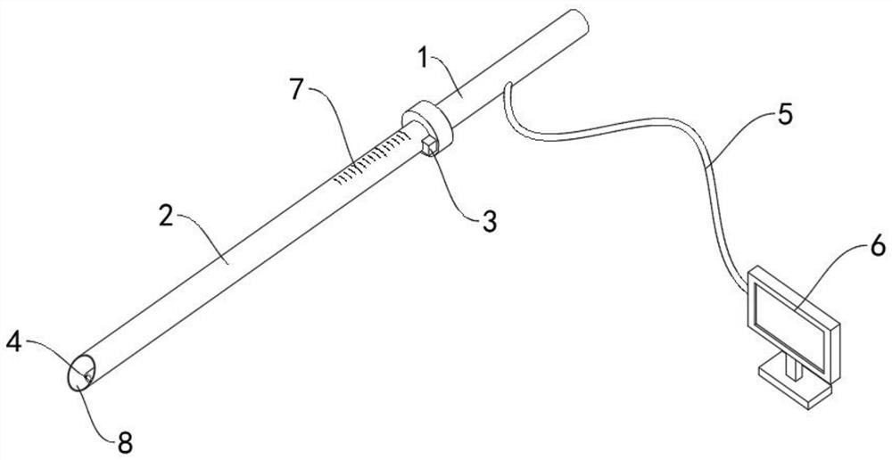
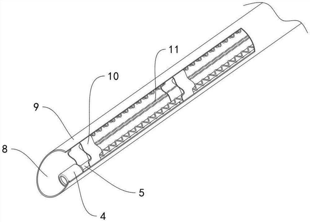
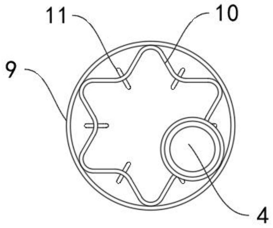
The invention discloses a visual bronchoscope. The visual bronchoscope comprises a connecting pipe, a tracheal catheter, a control device and a camera, wherein the tracheal catheter is connected withthe connecting pipe, the diameter of the tracheal catheter is variable, and the tracheal catheter is suitable for being inserted into the tracheal intubation; the control device is arranged at the connecting pipe, is connected with the tracheal catheter and is used for adjusting the diameter of the tracheal catheter; the camera is arranged at the position, away from the opening of the connecting pipe, of the tracheal catheter in the axial direction, a signal line is arranged on the camera, and the signal line is adhered to the inner side walls of the tracheal catheter and the connecting pipe and extends outwards to be connected with a display device. The visual bronchoscope is advantaged in that the tracheal catheter and the camera can guide retreating of the tracheal intubation, the situation that retreating of the tip end of the tracheal intubation is not in place, and the diameter of the tracheal catheter is variable is avoided, and when the diameter of the tracheal catheter is increased, the tracheal catheter can be used as a breather pipe; therefore, oxygen deficit of a patient caused when the tip of the trachea cannula retracts too much to the outside of the glottis can be avoided.

Description

Technical field[0001]The present invention relates to the field of medical equipment, in particular to a visual bronchoscope.Background technique[0002]Percutaneous tracheotomy is a technique often used in ICU to incise the trachea of ​​patients. In percutaneous tracheotomy, how to safely and conveniently exit the tracheal intubation that has occupied the airway space is a big problem that plagues clinicians. Specifically, if the tip of the tracheal tube that has occupied the airway space is not in place (the tip of the tracheal tube is not retracted to the position between the percutaneous tracheal puncture point and the glottis) , It will affect the insertion of the guide wire and puncture needle in percutaneous tracheostomy. The tube needs to be withdrawn repeatedly until the tip of the catheter is retracted to the position between the percutaneous tracheal puncture point and the glottis, which will affect the operation The process, leading to delay or failure of the operation; an...

Claims


Application Information

Patent Timeline
Patent Type & Authority Applications(China)
IPC IPC(8): A61B1/267A61B1/04A61M16/04
CPCA61B1/2676A61B1/04A61M16/0472
Inventor 李桂成李涛
Owner CHENZHOU NO 1 PEOPLES HOSPITAL
Learn More