Medical glass tube cleaning equipment

A technology for cleaning equipment and glass tubes, applied in the directions of cleaning hollow objects, cleaning methods and utensils, chemical instruments and methods, etc., can solve the problems of easily polluted glass tubes, low cleaning efficiency of glass tubes, etc., to prevent secondary pollution and save money. Cleaning time, effect of increasing stability

Pending Publication Date: 2021-02-12
周珂
View PDF1 Cites 2 Cited by
  • Summary
  • Abstract
  • Description
  • Claims
  • Application Information

AI Technical Summary

Problems solved by technology

[0005] In order to overcome the shortcomings of low glass tube cleaning efficiency and easy contamination of cleaned glass tubes, the technical problem to be solved is to provide a medical glass tube with high cleaning efficiency and no secondary pollution to the cleaned glass tubes cleaning equipment

Method used


Image

  • Medical glass tube cleaning equipment
  • Medical glass tube cleaning equipment
  • Medical glass tube cleaning equipment

Examples


Embodiment 1

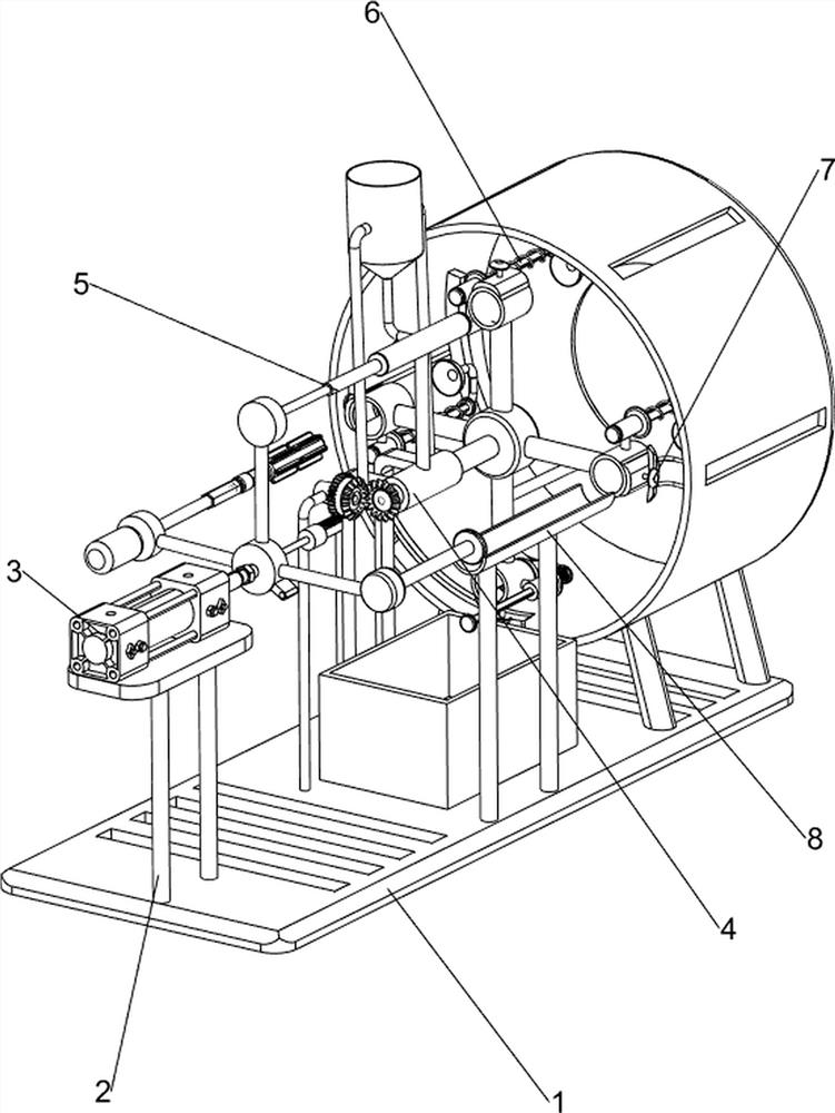
[0066] A medical glass tube cleaning equipment, such as Figure 1-5 As shown, it includes a base 1, a supporting platform 2, a pushing mechanism 3, a cleaning mechanism 4, and a rotating mechanism 5. The left side of the top of the base 1 is provided with a supporting platform 2, and the left side of the supporting platform 2 is provided with a pushing mechanism 3. A cleaning mechanism 4 is arranged in the middle of the top of the table 2, and the cleaning mechanism 4 is connected with the pushing mechanism 3, and the right side of the cleaning mechanism 4 is provided with a rotating mechanism 5.

[0067] When the medical staff needs to clean the glass tube, the medical staff puts the glass tube into the cleaning mechanism 4, and then starts the pushing mechanism 3. After the pushing mechanism 3 is started, it drives the rotating mechanism 5 to move to the right, and simultaneously drives the cleaning mechanism 4 to rotate. After the rotating mechanism 5 moves to the right pos...

Embodiment 2

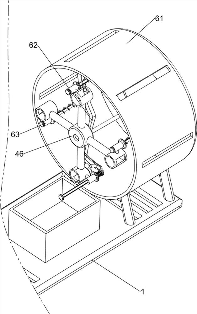
[0075] On the basis of Example 1, such as Figure 6-10 As shown, it also includes a blanking mechanism 6, a clamping mechanism 7 and a loading mechanism 8. The right side of the top of the base 1 is provided with a blanking mechanism 6, and the cleaning mechanism 4 and the blanking mechanism 6 are provided with a clamping mechanism 7. The base 1. A feeding mechanism 8 is arranged in the middle of the top, and the feeding mechanism 8 is located at the front side of the rotating mechanism 5.

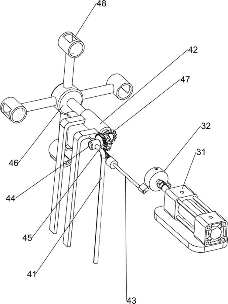
[0076] In order to clean the glass tube better, people can put the glass tube into the feeding mechanism 8, and drive the feeding mechanism 8 to move through the push plate 32, thereby pushing the glass tube into the material receiving block 48, and the clamping mechanism 7 can better The fixed glass tube, when the glass tube rotates to the lower side, will cooperate with the blanking mechanism 6, and the blanking mechanism 6 will push out the glass tube, so that people can better collect ...


PUM


Abstract

The invention relates to cleaning equipment, in particular to medical glass tube cleaning equipment. The medical glass tube cleaning equipment is high in cleaning efficiency and cannot cause secondarypollution to a cleaned glass tube. The medical glass tube cleaning equipment comprises a base, a supporting table, a pushing mechanism, a cleaning mechanism and a rotating mechanism, wherein the supporting table is arranged at the top of the base; the pushing mechanism is arranged at the top of the supporting table; the cleaning mechanism is arranged at the top of the supporting table and connected with the pushing mechanism; and the rotating mechanism is arranged on the cleaning mechanism. An air cylinder is started to drive a spring extension rod to move rightwards, so that water in a spraying pipe is sprayed out. A sponge block is driven to move rightwards to enter the glass tube, and then a motor is started to enable the sponge block to rotate to clean the glass tube, so that the glass tubes can be cleaned one by one. The air cylinder is closed, a push plate is driven to move leftwards, and a rotating rod is driven to rotate anticlockwise, and thus the glass tube is rotated to a cleaning position.

Description

technical field [0001] The invention relates to a cleaning device, in particular to a medical glass tube cleaning device. Background technique [0002] Hospitals use a large number of glass tubes every day, and these glass tubes are generally recyclable, and glass tubes need to be cleaned before recycling. [0003] For example, the patent application CN111389834A, open date 2020.07.10, discloses a glass tube cleaning device for manufacturing high borosilicate glass containers, including a support frame, a drive motor, a turret, a cleaning mechanism, a locking mechanism, a servo motor, a The cleaning process can fully clean the inner wall and outer wall of the glass tube at the same time, but after the device cleans the glass tube, it needs to shut down the equipment, and then manually take out the cleaned glass tube one by one, and then Put the glass tubes that need to be cleaned into the equipment one by one, which will cause low cleaning efficiency of the glass tubes and ...

Claims


Application Information

Patent Timeline
Patent Type & Authority Applications(China)
IPC IPC(8): B08B9/28B08B9/20B08B9/44
CPCB08B9/20B08B9/28B08B9/44
Inventor 周珂
Owner 周珂
Why Eureka
Try Eureka