Copper bar machining clamp
A technology of fixtures and copper bars, applied in the direction of manufacturing tools, metal processing, metal processing equipment, etc., can solve the problems of inability to adjust the processing points of copper bars, tedious manual operations, waste of time and manpower, etc.
- Summary
- Abstract
- Description
- Claims
- Application Information
AI Technical Summary
Problems solved by technology
Method used
Image
Examples
Embodiment 1
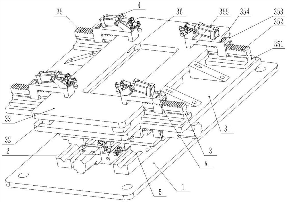
[0029] Embodiment 1: A fixture for processing copper bars, including: a base 1, a horizontal adjustment mechanism 2, a clamping and limiting mechanism 3 and a pressing mechanism 4, characterized in that,
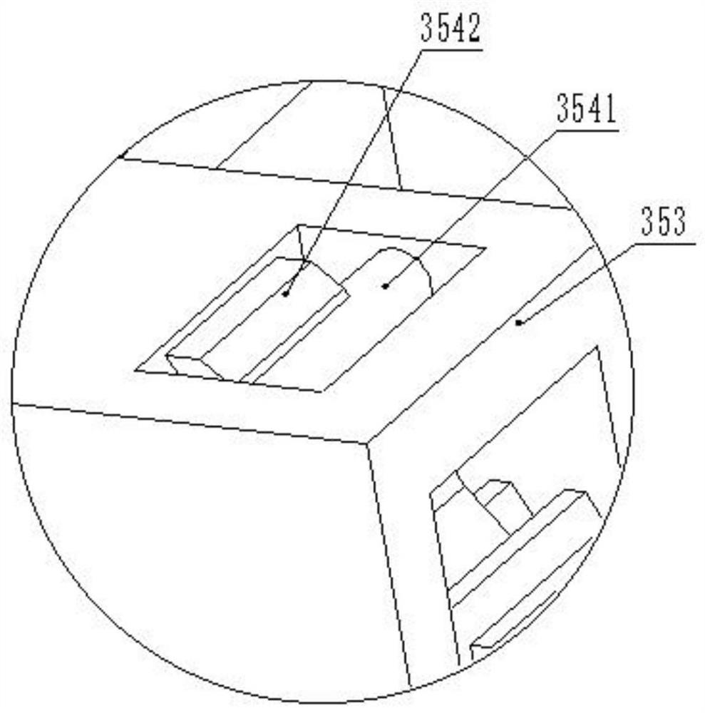
[0030] The base 1 is equipped with a horizontal adjustment mechanism 2, and the horizontal adjustment mechanism 2 is equipped with a clamping and limiting mechanism 3 for limiting the horizontal direction of the copper bars. Tight pressing mechanism 4, set in this way, horizontal adjustment mechanism 2 can adjust the position of copper bar adaptively, and adjust the processing hole position under the condition that the machining center remains unchanged, and clamping limit mechanism 3 is suitable for different types of The copper bars are fixed at the horizontal limit to ensure that a single fixture can process multiple types of copper bars. The clamping mechanism 4 compresses the copper bars to prevent the copper bars from moving. Install the clamping mechanism 4 on the clam...
Embodiment 2
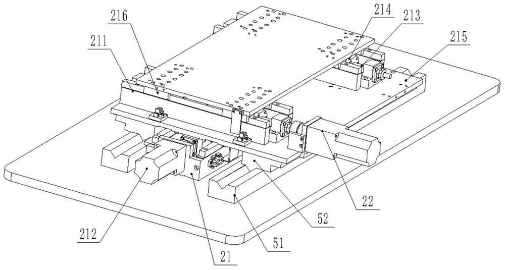
[0031] Embodiment 2: On the basis of Embodiment 1, the horizontal adjustment mechanism 2 includes: a horizontal movement mechanism 21 in direction one and a horizontal movement mechanism 22 in direction two. The motion trajectories of the horizontal moving mechanisms 22 are perpendicular to each other, and the horizontal moving mechanism 21 of the first direction and the horizontal moving mechanism 22 of the second direction have the same structure, so set up, through the cooperation of the horizontal moving mechanism 21 of the first direction and the horizontal moving mechanism 22 of the second direction, the alignment of the copper bars is realized. It can be moved freely on the level to facilitate the replacement of processing points.
Embodiment 3
[0032] Embodiment 3: On the basis of Embodiment 2, the description is made. The direction-horizontal movement mechanism 21 includes: guide rail 211, motor 212, threaded rod 213, internal thread slider 214, mobile platform 215 and mobile slider 216. Two guide rails 211 are arranged in parallel on the base 1, and a motor 212 is arranged on the base 1 at one end of the guide rails 211. The output end of the motor 212 is connected with one end of the threaded rod 213 through a connector, and the other end of the threaded rod 213 is installed on the guide rail through a bearing seat. On the base 1 at the other end of 211, the threaded rod 213 is covered with an internal thread slide block 214, a T-shaped groove is set in the movable slide block 216, the guide rail 211 is a T-shaped guide rail, and the lower end surface of the mobile platform 215 is installed on the guide rail through the movable slide block 216 211, the lower end surface of the mobile platform 215 is connected with ...
PUM
 Abstract
Description
Claims
Application Information
 - R&D
- Intellectual Property
- Life Sciences
- Materials
- Tech Scout
- Unparalleled Data Quality
- Higher Quality Content
- 60% Fewer Hallucinations
Browse by: Latest US Patents, China's latest patents, Technical Efficacy Thesaurus, Application Domain, Technology Topic, Popular Technical Reports.
© 2025 PatSnap. All rights reserved.Legal|Privacy policy|Modern Slavery Act Transparency Statement|Sitemap|About US| Contact US: help@patsnap.com


