Molding grinding wheel dresser

A molding grinding wheel and dresser technology, which is applied in the direction of abrasive surface adjustment devices, grinding machine parts, metal processing equipment, etc., can solve the problems of grinding wheel surface clogging, affecting grinding accuracy, and grinding wheel loss of cutting ability, etc., to achieve adaptable effect

Pending Publication Date: 2021-02-12
重庆强泰砂轮制造有限公司
View PDF0 Cites 3 Cited by
  • Summary
  • Abstract
  • Description
  • Claims
  • Application Information

AI Technical Summary

Problems solved by technology

[0002] During the grinding process, the abrasive grains of the grinding wheel are gradually rounded and blunt under the action of friction and extrusion, or when grinding tough materials, the abrasive debris is often embedded in the pores on the surface of the grinding wheel, making the grinding wheel The surface is clogged, and finally the grinding wheel will lose its cutting ability, which will cause work deformation and affect the grinding accuracy. In severe cases, burns and small cracks will appear on the grinding surface
[0003] During the grinding process of the workpiece with the forming grinding wheel, it must be trimmed in due course according to the wear condition of the forming grinding wheel, so as to restore the set shape accuracy and surface quality to ensure the grinding quality of the workpiece. The prior art Generally, diamond materials are used to grind the side of the grinding wheel, which increases the effective service life of the grinding wheel. However, because the grinding wheel will produce a large amount of fixed waste particles during the dressing and grinding process, the surrounding environment will be affected if it is not processed in time. At the same time, the temperature during the grinding process is relatively high. High, need to cool down in time

Method used


Image

  • Molding grinding wheel dresser
  • Molding grinding wheel dresser
  • Molding grinding wheel dresser

Examples


Embodiment Construction

[0020] The following will clearly and completely describe the technical solutions in the embodiments of the present invention with reference to the accompanying drawings in the embodiments of the present invention. Obviously, the described embodiments are only some, not all, embodiments of the present invention.

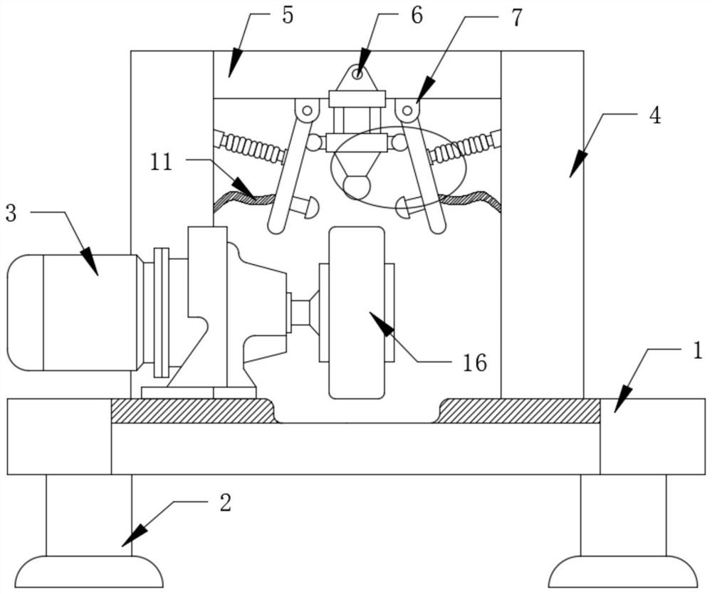
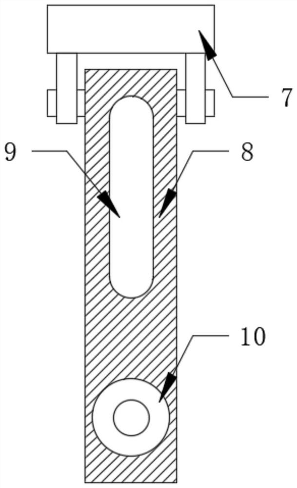
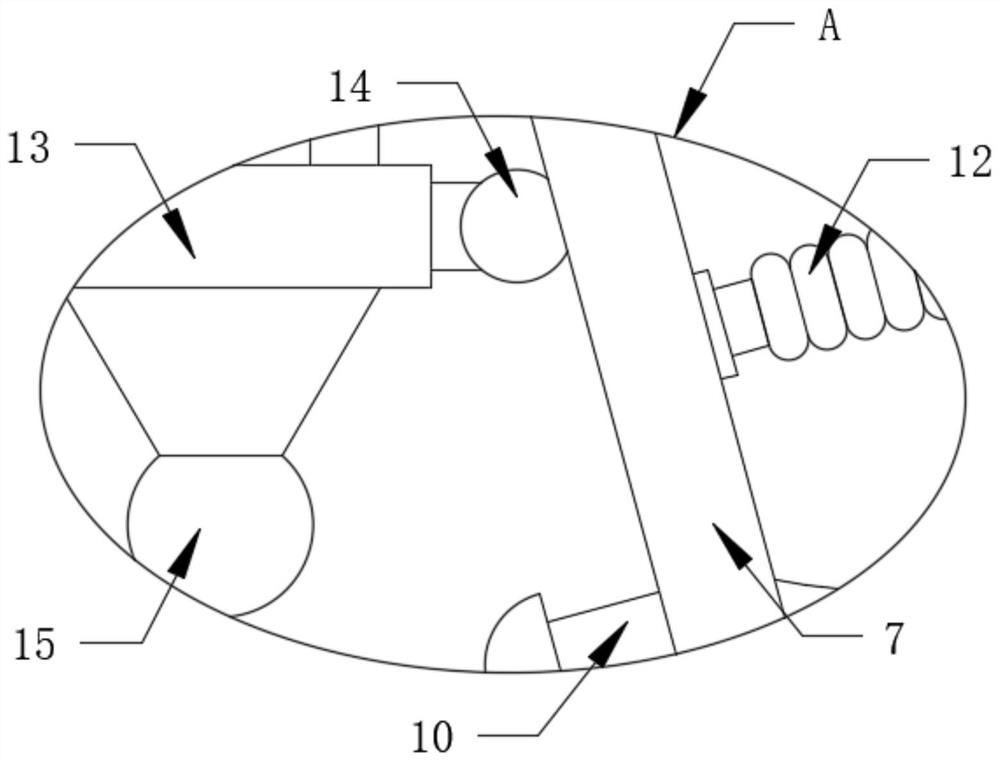
[0021] refer to Figure 1-3 , a forming grinding wheel dresser, comprising a workbench 1, support legs 2, a drive motor 3, a vertical column 4 and a top plate 5, the support legs 2 are fixedly connected to the lower end of the workbench 1, and the drive motor 3 is fixedly connected to the workbench 1 The upper surface of the drive motor 3 is model Y80M2-1, the vertical column 4 is fixedly connected to the upper end of the workbench 1 and is close to the outside of the drive motor 3, the top plate 5 is fixedly connected to the inner side of the vertical column 4, and the front of the top plate 5 is fixed A hydraulic cylinder 6 is connected. The model of the hydraulic ...


PUM


Abstract

The invention discloses a molding grinding wheel dresser which comprises a workbench, supporting legs, a driving motor, vertical columns and a top plate; the supporting legs are fixedly connected to the lower end of the workbench; the driving motor is fixedly connected to the upper surface of the workbench; the vertical columns are fixedly connected to the upper end of the workbench and is close to the outer side of the driving motor; the top plate is fixedly connected to the inner sides of the vertical columns, a hydraulic cylinder is fixedly connected to the front face of the top plate, anda grinding mechanism is installed at the lower end of the hydraulic cylinder; and installation bases are fixedly connected to the positions, close to the outer sides of the hydraulic cylinder, of thelower end of the top plate, and a moisturizing mechanism is installed at the lower ends of the installation bases. When the molding grinding wheel dresser is used, through cooperative use of a liftingbase, circular sliding blocks, a diamond pen and other structures, the effect of high adaptability is achieved, and through cooperative use of movable plates, atomizing spray heads, water inlet pipesand other structures, the effect of conveniently removing dust is achieved.

Description

technical field [0001] The invention belongs to the technical field of grinding wheel dressing, in particular to a forming grinding wheel dressing device. Background technique [0002] During the grinding process, the abrasive grains of the grinding wheel are gradually rounded and blunt under the action of friction and extrusion, or when grinding tough materials, the abrasive debris is often embedded in the pores on the surface of the grinding wheel, making the grinding wheel The surface is clogged, and finally the grinding wheel will lose its cutting ability, which will cause work deformation and affect the grinding accuracy. In severe cases, burns and small cracks will appear on the grinding surface. [0003] During the grinding process of the workpiece with the forming grinding wheel, it must be trimmed in due course according to the wear condition of the forming grinding wheel, so as to restore the set shape accuracy and surface quality to ensure the grinding quality of ...

Claims


Application Information

Patent Timeline
Patent Type & Authority Applications(China)
IPC IPC(8): B24B53/04B24B53/095
CPCB24B53/04B24B53/095
Inventor 李晓东
Owner 重庆强泰砂轮制造有限公司
Why Eureka
Try Eureka