
Feeding device for foaming machine and working method thereof

The technology of a feeding device and a foaming machine is applied in the field of foaming agent feeding equipment, which can solve the problems of gaps in the foaming place, increase the labor of workers, affect the foaming quality, etc., and achieve the effect of improving the foaming quality.

Inactive Publication Date: 2021-02-12
HANGZHOU JIATONG MACHINERY
View PDF0 Cites 0 Cited by
  • Summary
  • Abstract
  • Description
  • Claims
  • Application Information

AI Technical Summary

Problems solved by technology

[0004] The object of the present invention is to provide a feeding device for a foaming machine and its working method to solve the problem of the existing feeding device for a foaming machine. When feeding, the foaming material enters two rollers at one time Between the shafts, the foaming material cannot be uniformly transmitted, which affects the uniformity of the foaming material distribution, resulting in gaps in the foaming place, affecting the foaming quality; the existing feeding device for the foaming machine cannot make the two The distance between the two rollers changes, it is difficult to control the transmission speed of the foaming material, and the position of the transition plate extending into the transmission box cannot be adjusted, so it is difficult to realize the material transmission; the existing feeding material for the foaming machine The device cannot realize the recycling and reuse of the remaining materials, and the materials are easy to be wasted. The remaining materials need to be collected manually, which increases the labor load of workers and reduces the work efficiency.

Method used


Image

  • Feeding device for foaming machine and working method thereof
  • Feeding device for foaming machine and working method thereof
  • Feeding device for foaming machine and working method thereof

Examples


Embodiment Construction

[0030] The technical solutions of the present invention will be clearly and completely described below in conjunction with the embodiments. Apparently, the described embodiments are only some of the embodiments of the present invention, not all of them. Based on the embodiments of the present invention, all other embodiments obtained by persons of ordinary skill in the art without creative efforts fall within the protection scope of the present invention.

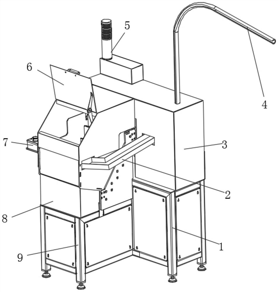
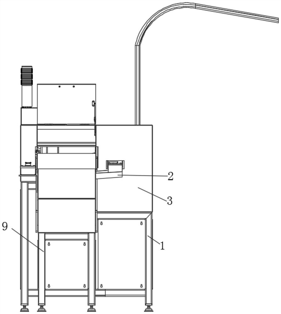
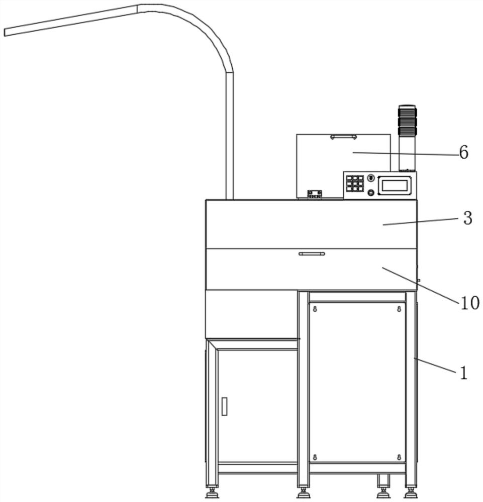
[0031] Such as Figure 1-6 As shown, a feeding device for a foaming machine includes a transmission frame 1 and a recovery frame 9, one side of the transmission frame 1 is provided with a recovery frame 9, the top of the transmission frame 1 is fixedly provided with a transmission box 3, and the recovery The top of the frame 9 is provided with a return box 8, the inner bottom surface of the return box 8 is provided with a transfer plate 20, the top end of the transfer plate 20 is provided with a support plate 13, and the si...


PUM


Abstract

The invention discloses a feeding device for a foaming machine. The feeding device comprises a conveying frame and a recycling frame, wherein the recycling frame is arranged on one side of the conveying frame, and a conveying box is fixedly arranged at the top of the conveying frame; a material returning box is arranged at the top of the recycling frame, and a conveying plate is arranged on the inner bottom surface of the material returning box; a supporting plate is arranged at one end of the top of the conveying plate; and a first motor is arranged on the side wall of the part, above the conveying plate, of the supporting plate. A fourth motor drives a conveying belt to operate, so that foaming materials can be conveyed to a pipeline connector. The output end of a second motor drives anauger to rotate, so that the materials can enter a filling pipe. The interior of a machined part can be filled with the foaming materials through the filling pipe. When the materials pass through theconveying belt, the excess foaming materials fall onto a recycling plate. After the excess materials enter the material returning box through the recycling plate, recycling of the excess materials isachieved, and waste of the materials is avoided. Manual excess material collection is not needed, the labor amount of workers is reduced, and the working efficiency is improved.

Description

technical field [0001] The invention relates to the field of foaming agent feeding equipment, in particular to a feeding device for a foaming machine and a working method thereof. Background technique [0002] A foaming machine, also known as a foam generator, is a device that makes foam from an aqueous solution of a foaming agent to a certain concentration. When the foaming machine is in use, it needs to be used with the feeding device. [0003] The existing feeding device for the foaming machine, when feeding, the foaming material enters between the two rollers at one time, resulting in the inability to uniformly transmit the foaming material and affecting the uniformity of the distribution of the foaming material. Causes gaps in the foaming area, which affects the foaming quality; the existing feeding device for the foaming machine cannot change the distance between the two rollers, it is difficult to control the transmission speed of the foaming material, and it is impo...

Claims


Application Information

Patent Timeline
Patent Type & Authority Applications(China)
IPC IPC(8): B29C44/34
CPCB29C44/3442
Inventor 魏旭东廖建光沈立峰
Owner HANGZHOU JIATONG MACHINERY
Learn More