Forming machine for vacuum insulated panel

A technology for vacuum insulation panels and molding machines, which is applied to presses, manufacturing tools, etc. It can solve the problems of small exhaust channel aperture and exhaust area, damage to the mold drawing cylinder, and low exhaust efficiency, so as to improve accuracy and Stability, blocking core material leakage, and improving exhaust efficiency

Active Publication Date: 2014-01-22
QUANZHOU SANJIA MACHINERY
View PDF9 Cites 4 Cited by
  • Summary
  • Abstract
  • Description
  • Claims
  • Application Information

AI Technical Summary

Problems solved by technology

The above-mentioned automatic powder compaction molding machine is not suitable for pressing nano-scale microporous inorganic materials (such as short glass fibers, fumed silicon, etc.), because: (1) For nano-scale microporous inorganic materials, the pressing process The pressing force of the upper mold required in the patented hydraulic molding machine is relatively high, and the lower mold is in a jacked-up state during the pressing molding process of the patented hydraulic molding machine, which is easy to damage the drawing cylinder under the lower mold; (2) During the pressing process of the material, The amount of exhausted gas is large. Using this equipment and its process for pressing and exhausting, the exhausting effect is poor, and effective pressing operations cannot be realized.
[0004] In addition, the Chinese patent with the publication number CN 1501312A discloses a metal mold that can be vented, but this metal mold is also not suitable for treating nano-scale microporous inorganic materials (such as short glass fibers, fumed silicon, etc.) In the molding machine for pressing, the reasons are: (1) Since the exhaustable metal mold is mainly used for pressing powder materials, the pore size of the fiber permeable layer is very small, and the gas in the mold cavity finally passes through the exhaust T

Method used


Image

  • Forming machine for vacuum insulated panel
  • Forming machine for vacuum insulated panel
  • Forming machine for vacuum insulated panel

Examples


Embodiment approach

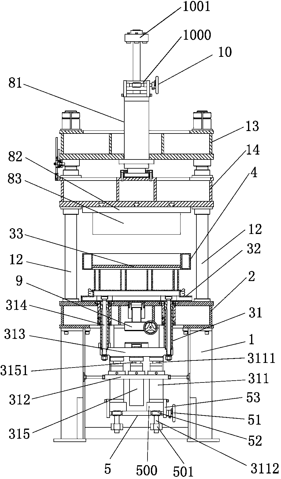
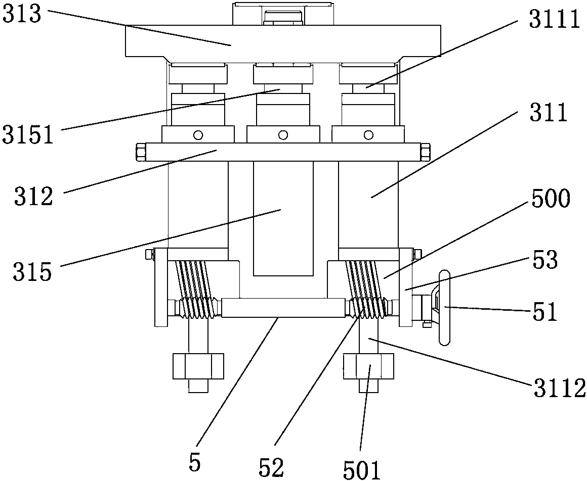
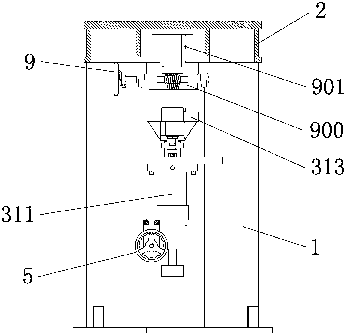
[0038] combine figure 1 , 5 ~8, a molding machine for vacuum insulation panels, including a frame 1, a lower support device 2 is erected on the frame 1, a lower mold base 32 can be lifted and lowered on the lower support device 2, and a lower mold core 33 is installed on the lower mold base 32 above; the upper mold core 83 is set correspondingly above the lower mold core 33, the middle mold frame 4 is set between the upper mold core 83 and the lower mold core 33, and the upper mold core 83 and the lower mold core 33 slide through the middle mold frame 4 The upper mold core 83, the middle mold frame 4, the lower mold core 33 and the lower mold base 32 are all internal hollow structures, and the upper mold core bottom plate 830, the middle mold frame inner plate 40 and the lower mold core top plate 330 are all provided with through holes The first exhaust channel 15, an exhaust plug 16 is inserted in the first exhaust channel 15 close to the outside, and the second exhaust chan...


PUM

PropertyMeasurementUnit
Thicknessaaaaaaaaaa

Abstract

The invention provides a forming machine for a vacuum insulated panel. The forming machine for the vacuum insulated panel comprises a machine frame, a lower supporting device is arranged on the machine frame in an erecting mode, a lower die base is arranged on the lower supporting device in a lifting and erecting mode, and a lower die core is installed on the lower die base. An upper die core, a middle die frame, the lower die core and the lower die base are hollow. A bottom plate of the upper die core, an inner side plate of the middle die frame and a top plate of the lower die core are respectively provided with a communicated first exhaust passage, and a venting plug is inserted into the first exhaust passage close to the outer side and is fully provided with second exhaust passages. The lower die base is communicated with the lower die core. The outer side wall of the upper die core, the outer side wall of the middle die frame and the outer side wall of the lower die base are provided with third exhaust passages communicated with the outside. The forming machine is good in supporting stability, high in exhaust efficiency, capable of bearing large pressing force, suitable for pressing the vacuum insulated panel and high in safety coefficient, and the venting plug is convenient to dismount and replace.

Description

technical field [0001] The invention belongs to the field of forming machines, in particular to a forming machine for vacuum insulation panels. Background technique [0002] In recent years, vacuum insulation panels have been widely used to insulate refrigerators, aviation, incubators, refrigerated vehicles and external walls due to their ultra-thin, light weight, fireproof and non-combustible properties, and good thermal insulation properties. However, since the core material of vacuum insulation panels is mostly composed of ultra-fine short glass fibers and fumed silicon, these materials have small particle sizes and large specific surface areas, and the three-dimensional cross-winding between fibers will produce a large number of internal and external connections. The tiny pores and holes in the vacuum insulation panel product will generate a lot of gas during the forming process, making the automatic pressing operation impossible. Therefore, the existing vacuum insulati...

Claims


Application Information

Patent Timeline
IPC IPC(8): B30B15/02
Inventor 程在足
Owner QUANZHOU SANJIA MACHINERY
Why Eureka
Try Eureka