
Application method of hydraulic energy storage system of new-energy electric heavy-duty mine truck

A heavy-duty mining and hydraulic energy storage technology, which is applied to accumulator devices, engines, machines/engines, etc., can solve problems such as the inability to convert gravitational potential energy into electrical energy, and achieve the effect of improving battery life and making up for electrical energy loss

Pending Publication Date: 2021-02-12
四川中力汇通新能源汽车有限公司
View PDF0 Cites 0 Cited by
  • Summary
  • Abstract
  • Description
  • Claims
  • Application Information

AI Technical Summary

Problems solved by technology

[0002] The hydraulic energy storage system can convert the energy in the system into compression energy or potential energy for storage. When the system needs it, the stored energy can be released to replenish the system. The hydraulic energy storage device is mainly used in the hydraulic system for system pressure maintenance, To ease the impact pressure, absorb the pulse pressure and act as an emergency energy source, the existing mine dump truck is generally equipped with a hydraulic energy storage WEC power generation system to cooperate with the power supply system of the mine dump truck. However, the existing hydraulic energy storage WEC power generation system Only the potential energy of the vehicle when going downhill and braking can be converted into electrical energy, but the gravitational potential energy of the vehicle when going uphill cannot be converted into electrical energy. Therefore, we propose a new energy electric heavy-duty mining vehicle hydraulic energy storage system application method

Method used


Image

  • Application method of hydraulic energy storage system of new-energy electric heavy-duty mine truck

Examples


Embodiment Construction

[0022] In order to make the object, technical solution and advantages of the present invention clearer, the present invention will be further described in detail below in conjunction with specific embodiments. It should be understood that the specific embodiments described here are only used to explain the present invention, not to limit the present invention. Based on the embodiments of the present invention, all other embodiments obtained by persons of ordinary skill in the art without making creative efforts belong to the protection scope of the present invention.

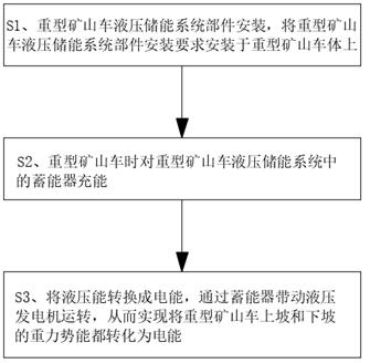
[0023] The present invention provides such as figure 1 An application method of a new energy electric heavy-duty mining vehicle hydraulic energy storage system, comprising the following steps:

[0024] S1. Installation of hydraulic energy storage system components for heavy mining vehicles. The installation requirements for the hydraulic energy storage system components of heavy mining vehicles are installed on...


PUM


Abstract

The invention discloses an application method of a hydraulic energy storage system of a new energy electric heavy-duty mine truck. The method comprises the following steps: S1, mounting components ofthe hydraulic energy storage system of the heavy-duty mine truck, namely mounting the components of the hydraulic energy storage system of the heavy-duty mine truck on a heavy-duty mine truck body according to mounting requirements; S2, charging energy to an energy accumulator in the hydraulic energy storage system of the heavy-duty mine truck; and S3, converting the hydraulic energy into electricenergy, and driving a hydraulic generator to operate through the energy accumulator, so as to convert the gravitational potential energy generated when the heavy-duty mine truck goes uphill and downhill into the electric energy. When the mine dump truck runs, gravitational potential energy generated when the truck goes uphill and downhill can be converted into electric energy, the potential energy can be converted into the electric energy when the truck goes uphill and downhill in this way, huge electric energy loss generated when the electric heavy-duty truck goes uphill can be made up for,and the endurance capacity of the heavy-duty truck going uphill is improved.

Description

technical field [0001] The invention belongs to the field of hydraulic energy storage systems of new energy electric heavy-duty mining vehicles, and more specifically relates to an application method of the hydraulic energy storage system of new energy electric heavy-duty mining vehicles. Background technique [0002] The hydraulic energy storage system can convert the energy in the system into compression energy or potential energy for storage. When the system needs it, the stored energy can be released to replenish the system. The hydraulic energy storage device is mainly used in the hydraulic system for system pressure maintenance, To ease the impact pressure, absorb the pulse pressure and act as an emergency energy source, the existing mine dump truck is generally equipped with a hydraulic energy storage WEC power generation system to cooperate with the power supply system of the mine dump truck. However, the existing hydraulic energy storage WEC power generation system ...

Claims


Application Information

Patent Timeline
Patent Type & Authority Applications(China)
IPC IPC(8): F03G3/00F15B1/027
CPCF03G3/00F15B1/027
Inventor 张园尚彭梓耕
Owner 四川中力汇通新能源汽车有限公司
Learn More