Submersible pump machine facilitating control of motor power supply system

A technology of motor power supply and pump machine, which is applied to the components of the pumping device for elastic fluid, machine/engine, pump, etc. effect of time, faster air flow, faster evaporation

Inactive Publication Date: 2021-02-12
南安森威工业产品设计有限公司
View PDF0 Cites 1 Cited by
  • Summary
  • Abstract
  • Description
  • Claims
  • Application Information

AI Technical Summary

Problems solved by technology

[0002] The submersible pump unit is an important equipment for extracting groundwater. When in use, the submersible pump unit is submerged into the groundwater to work, connected to the power system through wires, and the working status of the unit is controlled through the switch of the power system. The blade rotates, and the liquid enters the water inlet pipe and is discharged to the outlet pipe after being lifted by the blade rotation. In order to reduce the sediment at the botto

Method used


Image

  • Submersible pump machine facilitating control of motor power supply system
  • Submersible pump machine facilitating control of motor power supply system
  • Submersible pump machine facilitating control of motor power supply system

Examples


Embodiment 1

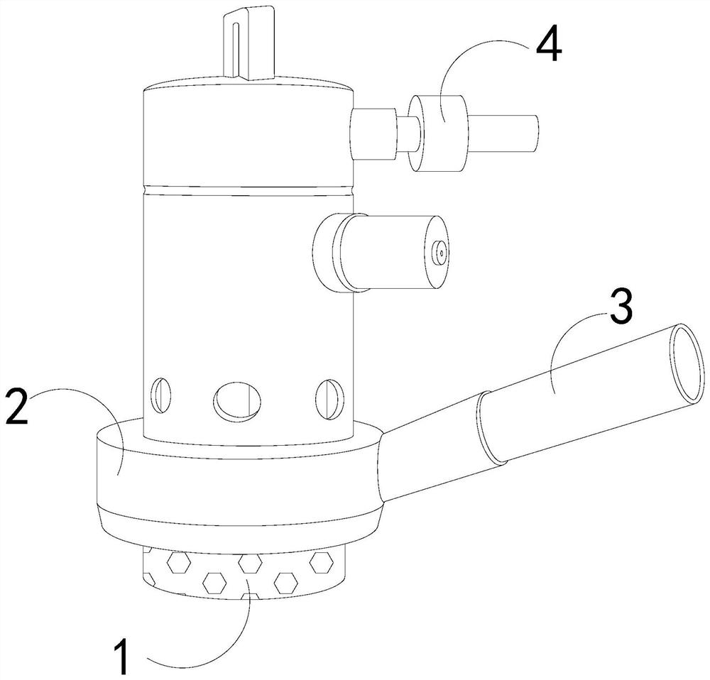
[0027] as attached figure 1 To attach Figure 5 Shown:

[0028] The present invention provides a submersible pump that is convenient to control the motor power supply system. Its structure includes a base 1, a pump body 2, a water inlet pipe 3, and a water outlet pipe 4. The pump body 2 is vertically welded on the top of the base 1, and the water inlet pipe 3 It is obliquely installed on the right side of the pump body 2, and the outlet pipe 4 is horizontally fixed on the right side of the top of the pump body 2.

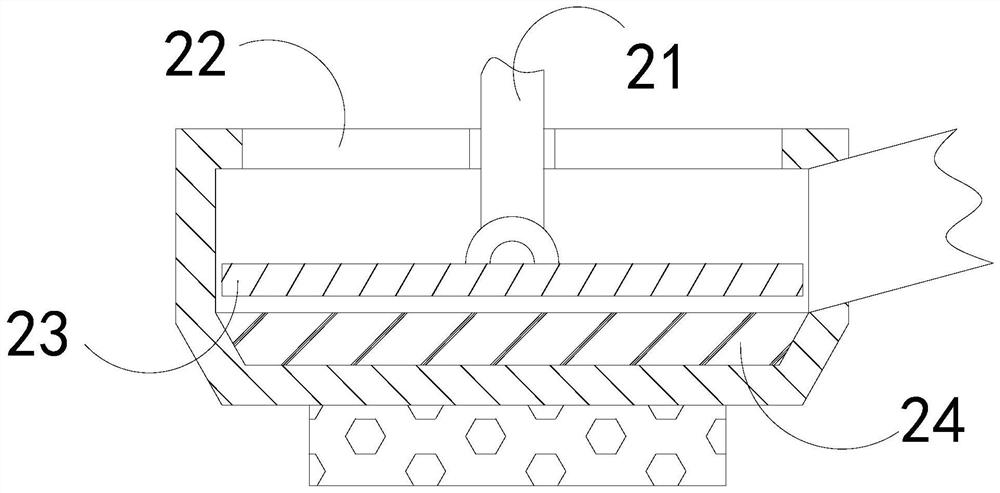
[0029] The pump body 2 is provided with a bearing 21, a water outlet 22, a blade 23, and a pushing mechanism 24. The bearing 21 runs through the center of the top of the pump body 2, and the water outlet 22 runs through the top surface of the pump body 2 and is located on both sides of the bearing 21. On the side, the vane 23 is fixed on the bottom of the bearing 21 , and the pushing mechanism 24 is sleeved on the inner bottom of the pump body 2 .

[0030] Wherei...

Embodiment 2

[0036] as attached Image 6 To attach Figure 8 Shown:

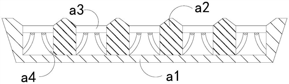
[0037] Wherein, the support block a2 is provided with a swing plate n1, a clamping block n2, an inner cavity n3, and a support bar n4, the swing plate n1 is located on both sides of the support block a2, and the clamp n2 is embedded and fixed on the inner surface of the swing plate n1 , the inner cavity n3 is located inside the support block a2, the support bar n4 is connected to the top of the swing plate n1, and the support bar n4 is made of rubber material with elasticity, which is conducive to pushing the swing plate n1 to both sides and speeding up the swing plate n1 is in active cooperation with the laminating plate s4, and the inner side of the oscillating plate n1 has an uneven surface, which is conducive to increasing the contact area with the gas in the inner cavity n3 and accelerating the diffusion of the gas in the inner cavity n3.

[0038]Wherein, the support bar n4 is provided with a swing rod r1, a reset...


PUM


Abstract

The invention discloses a submersible pump machine facilitating control of a motor power supply system. The submersible pump machine structurally comprises a base, a pump body, a water inlet pipe anda water outlet pipe, the pump body is vertically welded to the top of the base, the water inlet pipe is obliquely installed on the right side of the pump body, the water outlet pipe is horizontally fixed to the right side of the top end of the pump body, the pump body is provided with a bearing, a water inlet, blades and a pushing mechanism, the bearing penetrates through the center of the top ofthe pump body, due to the fact that the water inlet pipe is inclined, after underground water pumping is stopped, liquid lower than the blades in the pump body cannot be discharged to the water inletpipe in time, the liquid lower than the blades at the bottom in the pump body is pushed upwards and diffused through the pushing mechanism, so that long-term retention of the liquid at the bottom in the pump body is reduced, and the use time of a submersible pump is prolonged, and due to the fact that liquid diffuses along with the blades and is retained on the inner wall of the pump body, so thatgas in a supporting block diffuses towards the interior of the pump body through movable fit of the supporting block and a push plate, air flowing in the pump body is accelerated, and evaporation ofmoisture of the liquid retained on the inner wall of the pump body is accelerated.

Description

technical field [0001] The invention belongs to the field of power supply systems, and more specifically relates to a submersible pump that is convenient for controlling a motor power supply system. Background technique [0002] The submersible pump unit is an important equipment for extracting groundwater. When in use, the submersible pump unit is submerged into the groundwater to work, connected to the power system through wires, and the working status of the unit is controlled through the switch of the power system. The blade rotates, and the liquid enters the water inlet pipe and is discharged to the outlet pipe after being lifted by the blade rotation. In order to reduce the sediment at the bottom of the pool from entering the water inlet pipe, the water inlet pipe is at an inclined angle; in the prior art, a submersible pump unit is used to pump groundwater , Because the water inlet pipe is inclined, after the pumping of groundwater is stopped, the liquid below the bla...

Claims


Application Information

Patent Timeline
IPC IPC(8): F04D29/00F04D13/08
CPCF04D13/08F04D29/007
Inventor 陈金秋
Owner 南安森威工业产品设计有限公司
Why Eureka
Try Eureka