Double-effect control valve
A technology for controlling valves and valve control, applied in the field of double-effect control valves, can solve problems such as inconvenience, and achieve the effects of delaying deposition speed, easy operation and simple structure
- Summary
- Abstract
- Description
- Claims
- Application Information
AI Technical Summary
Problems solved by technology
Method used
Image

Examples
Embodiment 1
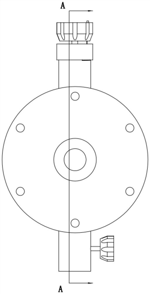
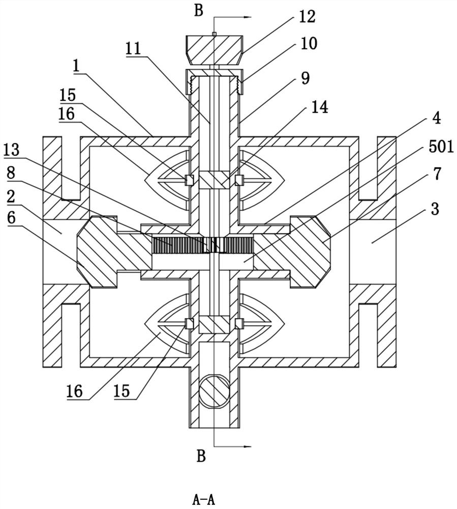
[0029] A double-effect control valve, refer to Figure 1-Figure 3 As shown, it includes a hollow valve body 1 and an outlet 3 of an inlet 2 located at both ends of the valve body 1. A valve control part is arranged in the valve body 1. The valve control part includes a horizontally arranged conduit 4, and a sealing guide is arranged in the conduit 4. The guide rod 5 and the inlet plug 6 and the outlet plug 7 that are respectively matched with the inlet 2 and the outlet 3 at both ends of the guide rod 5 are provided outside the guide rod 5 with an elastic layer to ensure its sealing and moving cooperation with the conduit 4, Between the conduit 4 and the valve body 1, there is a driving part that drives the guide rod 5 to move. The drive part includes a drive tube 9 that extends vertically from the outer wall of the conduit 4 to the outer wall of the valve body 1 and communicates with the inside of the conduit 4, on the guide rod 5. A fitting groove 501 extending axially along ...
Embodiment 2
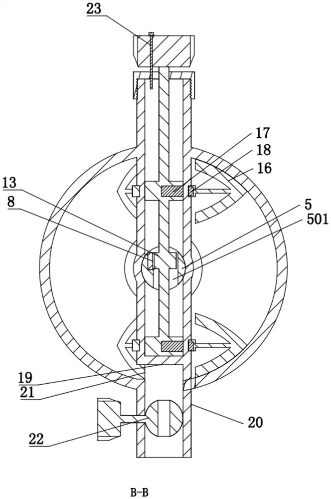
[0035] This embodiment is aimed at the situation that the flow in the valve body has been blocked by deposits in the valve body, and an improvement is made on the basis of embodiment 1. Refer to Figure 4 As shown, the guide rod 5 includes a middle section 502 and a fitting section 503 fixed to the inlet plug 6 and the outlet plug 7 respectively. An elastic layer is arranged on the outer wall of the fitting section 503 so as to ensure that it is always in a sealed movement with the catheter 4 during its movement. In the matched state, the matching groove 501 is located on the middle section 502, and an electromagnetic control mechanism is arranged between the matching section 503 and the middle section 502. The plugs 7 block the inlet 2 and the outlet 3 respectively, and a sealed cavity is formed inside the valve body at this time, so that lateral movement of deposits can be avoided.
[0036] The concrete setting of electromagnetic control mechanism is, comprises the electromagn...
PUM
 Abstract
Description
Claims
Application Information