

Rotary kiln for hazardous waste incineration
A rotary kiln and hazardous waste technology, applied in the direction of incinerator, combustion type, combustion method, etc., can solve the problems of uneven heating of hazardous waste, inability to achieve stirring and mixing, and affect the efficiency of hazardous waste incineration, so as to achieve the improvement effect and improvement effect and efficient, effective and efficient results
- Summary
- Abstract
- Description
- Claims
- Application Information
AI Technical Summary
Problems solved by technology
Method used
Image

Examples
Embodiment 1
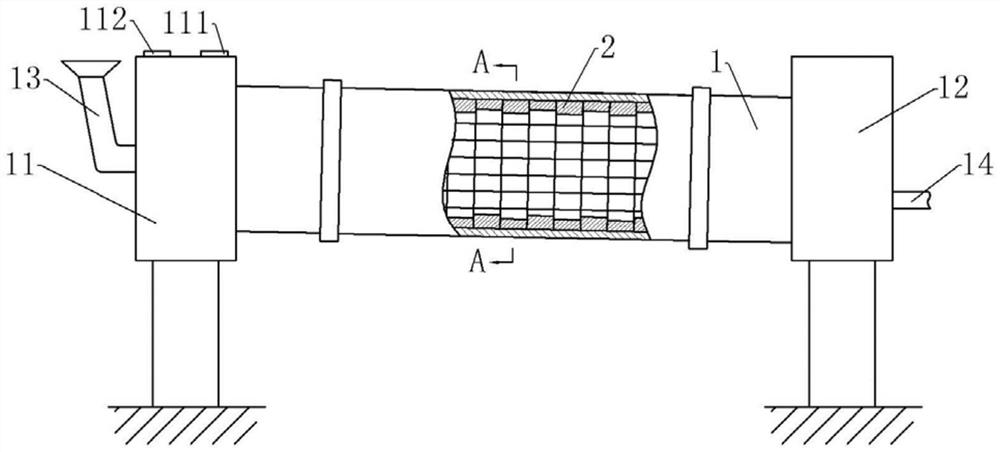
[0042] Rotary kiln for hazardous waste incineration, basically as attached figure 1 As shown, it includes a support frame and a cylinder body 1 that is rotatably connected to the support frame. The cylinder body 1 is inclined downward from left to right, and the inclination angle of the cylinder body 1 is set according to actual needs. In this embodiment, the cylinder body 1 The angle of inclination is 10°. A motor is also fixed on the support frame, a driving gear is coaxially fixed on the drive shaft of the motor, and a driven ring gear meshed with the driving gear is fixed coaxially outside the cylinder body 1, so that the motor can drive the driving gear to rotate, and through The transmission of the movable ring gear realizes the rotation of the cylinder body 1 .
[0043]The left end of the cylinder body 1 is rotatably connected with a kiln head cover 11, and the right end of the cylinder body 1 is rotatably connected with a kiln tail cover 12. There is a ring of static ...
Embodiment 2
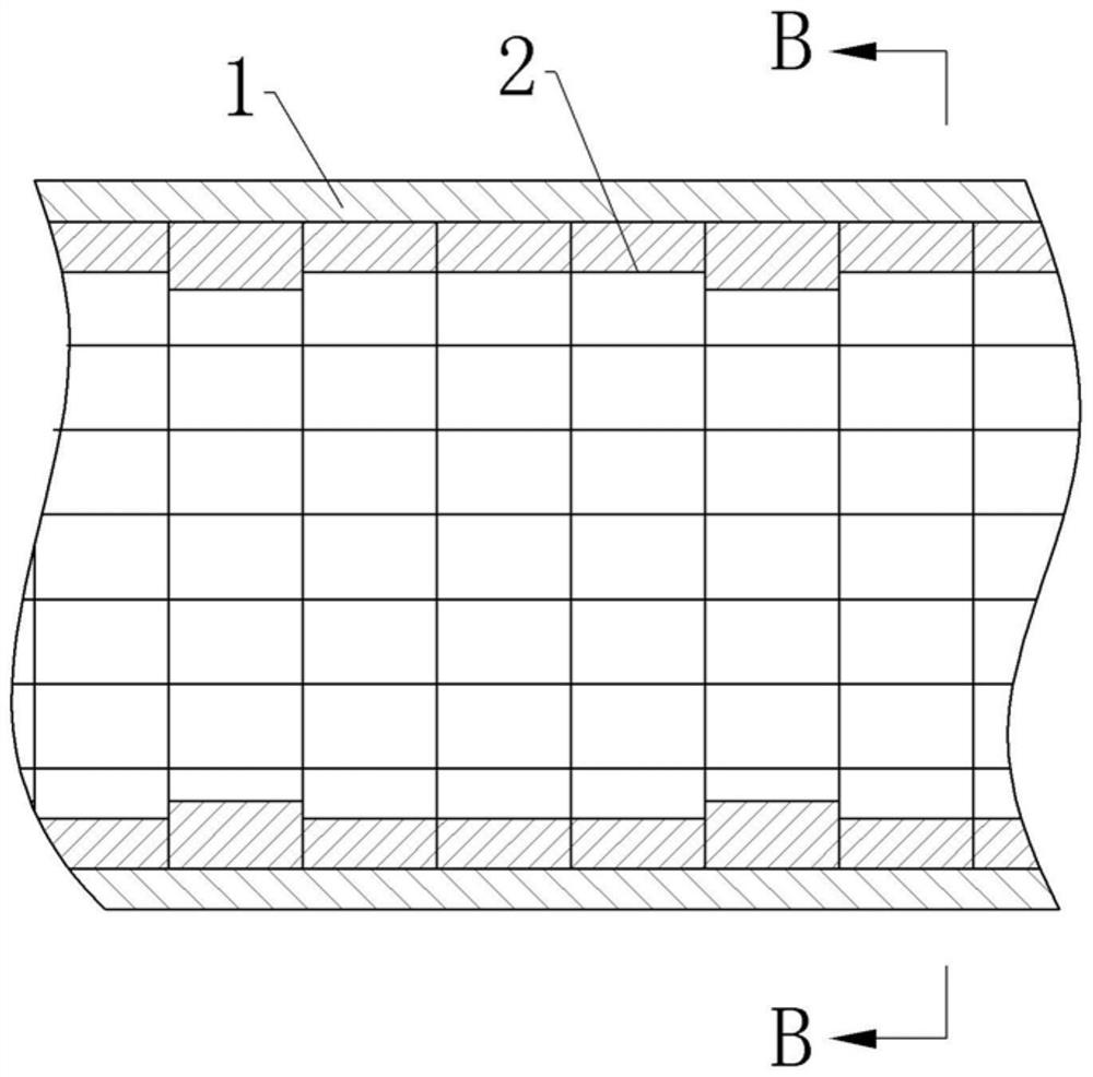
[0054] The difference between embodiment 2 and embodiment 1 is that each material dispersion structure in this embodiment includes 11 groups of refractory bricks, and each group of refractory bricks includes a higher refractory brick 2 and a lower refractory brick. Brick 2, the height difference between the higher refractory brick 2 and the lower refractory brick 2 is 100mm, and all adjacent to the higher refractory brick 2 are lower refractory bricks 2; that is, each material dispersion structure The refractory bricks 2 are arranged in cycles according to the manner of a, a+100mm, a...a, a+100mm.
[0055] In this embodiment, each group of material dispersion structures includes a higher material dispersion structure and a lower material dispersion structure, and the height difference between the higher material dispersion structure and the lower material dispersion structure is 100mm; The adjacent material dispersion structures are all lower material dispersion structures. T...
Embodiment 3
[0058] Embodiment 3 differs from Embodiment 1 only in that, as Figure 4 As shown, in this embodiment, each material dispersion structure includes 8 groups of refractory bricks, and each group of refractory bricks includes a higher refractory brick 2 and three lower refractory bricks 2, and the higher refractory brick 2 and The height difference of the lower refractory bricks 2 is 50mm, and all the adjacent refractory bricks 2 are lower refractory bricks 2; , a+50mm, a.....a+50mm, a, a, a, a+50mm cycle setting.
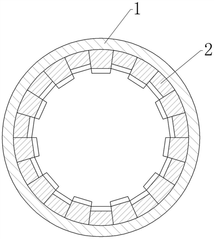
[0059] to combine image 3 As shown, each group of material dispersion structures in this embodiment includes a higher material dispersion structure and three lower material dispersion structures, and the height difference between the higher material dispersion structure and the lower material dispersion structure is 50 mm. And adjacent to the higher material dispersion structure are lower material dispersion structures. Mark a lower material dispersion structure a...
PUM
 Abstract
Description
Claims
Application Information