Magnetic regenerator, cold accumulation bed, magnetic refrigeration system and magnetic refrigeration control method

A control method and magnetic cold storage technology, applied in the fields of magnetic refrigeration system and magnetic refrigeration control, magnetic cold accumulator, cold storage bed, can solve the problems of system performance decline, poor adaptability of magnetic working medium, reduction of magneto-caloric effect, etc.

Active Publication Date: 2021-02-12
GREE ELECTRIC APPLIANCES INC
View PDF6 Cites 2 Cited by
  • Summary
  • Abstract
  • Description
  • Claims
  • Application Information

AI Technical Summary

Problems solved by technology

[0006] Therefore, in order to increase the temperature span of the regenerator, the regenerator should be filled with a variety of magnetic working fluids with different Curie temperatures, and from the hot end to the cold end of the regenerator, the Curie temperature of the magnetic working fluid decreases, which will increase the temperature of the cold storage. The temperature span of the regenerator, but the following problems will arise: Although the multi-layer magnetic working medium will increase the temperature span of the regenerator, it will reduce the cooling capacity of the regenerator at a low temperature. For example, under the condition of the maximum cooling capacity of the system, the temperature span is 0°C , the temperature of the magnetic working medium in the cold storage bed is the same, which determines that only one kind of magnetic working medium can be placed in the cold storage bed. The difference in working temperature is large, the magnetic working medium does not work at the optimal point, and the cooling capacity is low
The Cu

Method used


Image

  • Magnetic regenerator, cold accumulation bed, magnetic refrigeration system and magnetic refrigeration control method
  • Magnetic regenerator, cold accumulation bed, magnetic refrigeration system and magnetic refrigeration control method
  • Magnetic regenerator, cold accumulation bed, magnetic refrigeration system and magnetic refrigeration control method

Examples


Embodiment Construction

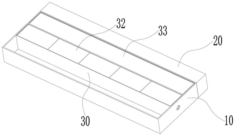
[0084] see in conjunction Figure 3 to Figure 8 As shown, according to the embodiment of the present application, the magnetic cold storage includes a first magnetocaloric unit 33 and a second magnetocaloric unit 32, the first magnetocaloric unit 33 and the second magnetocaloric unit 32 are arranged side by side, and the first magnetocaloric unit 33 Comprising a single magneto-caloric material, the two ends of the first magneto-caloric unit 33 along the fluid flow direction are respectively provided with first interfaces 31b, the second magneto-caloric unit 32 includes a multi-layer magneto-caloric material, and the multi-layer magneto-caloric material flows along the fluid The directions are set in sequence, and the two ends of the second magnetocaloric unit 32 along the fluid flow direction are respectively provided with second ports 31a.

[0085] The magnetic regenerator of the present application uses at least two magnetocaloric units arranged side by side, one of which us...


PUM


Abstract

The invention provides a magnetic regenerator, a cold accumulation bed, a magnetic refrigeration system and a magnetic refrigeration control method. The magnetic regenerator comprises a first magneticheating unit (33) and a second magnetic heating unit (32); the first magnetic heating unit (33) and the second magnetic heating unit (32) are arranged side by side; the first magnetic heating unit (33) comprises a single magnetic heating material; first connectors (31b) are formed in the two ends, in the fluid flowing direction, of the first magnetic heating unit (33); the second magnetic heatingunit (32) comprises multiple layers of magnetic heating materials; the multiple layers of magnetic heating materials are sequentially arranged in the fluid flowing direction; and second connectors (31a) are formed in the two ends, in the fluid flowing direction, of the second magnetic heating unit (32). According to the magnetic regenerator, the adaptability of the magnetic regenerator to the environment temperature can be improved, and the magnetic regenerator can be kept in a good working state within different temperature span ranges.

Description

technical field [0001] The present application relates to the technical field of magnetic refrigeration, in particular to a magnetic cold storage device, a cold storage bed, a magnetic refrigeration system and a magnetic refrigeration control method. Background technique [0002] Magnetic refrigeration technology is a high-tech refrigeration technology, which has been attracting attention both at home and abroad in recent years. Magnetic refrigeration does not rely on gas compression and expansion to change the phase of the working medium to achieve refrigeration like traditional refrigeration technology, nor does it require substances that are likely to cause the destruction of the atmospheric ozone layer and the application of complex gas compressors and other equipment. The reversible magnetocaloric effect of the refrigeration material, also known as the Magnetic Card Effect (Magnetocaloric Effect, MCE), means that the magnetic refrigeration material releases heat to the ...

Claims


Application Information

Patent Timeline
IPC IPC(8): F25B21/00
CPCF25B21/00F25B2321/002Y02B30/00
Inventor 王振雨李大全杨蓉罗胜汪魁
Owner GREE ELECTRIC APPLIANCES INC
Why Eureka
Try Eureka