
Automatic water testing device for pipeline machining

A water testing device and automatic technology, applied in the direction of applying stable tension/pressure to test material strength, saving water, measuring devices, etc., can solve the problems of high labor intensity for operators, complicated and difficult operation, and low practicability, and achieve Widen usage scenarios and scope, simple and convenient operation, and improve production efficiency

Active Publication Date: 2021-02-12
湖南瑞邦管业有限公司
View PDF3 Cites 4 Cited by
  • Summary
  • Abstract
  • Description
  • Claims
  • Application Information

AI Technical Summary

Problems solved by technology

[0002] After the steel pipe is produced, it needs to be tested for water testing, mainly for the sealing performance and pressure bearing capacity of the steel pipe. At present, most of the steel pipe water testing methods are to place the produced steel pipe on the fixed frame first, and then use the blind Temporarily seal the two ends of the steel pipe with the plate, and finally use the pressure test pump to inject water and pressurize the inside of the pipe to check whether its sealing performance and pressure capacity are qualified. Because the quality and volume of the steel pipe are large, it is inconvenient to move it. The operation of installing and removing the blind plate before and after is complicated and difficult, and the labor intensity of the operators is relatively high, and the water in the pipeline after the water test is inconvenient to recycle, causing a lot of waste of water resources, it is not convenient for continuous water test experiments, and the practicability is low

Method used


Image

  • Automatic water testing device for pipeline machining
  • Automatic water testing device for pipeline machining
  • Automatic water testing device for pipeline machining

Examples


Embodiment Construction

[0022] The following will clearly and completely describe the technical solutions in the embodiments of the present invention with reference to the accompanying drawings in the embodiments of the present invention. Obviously, the described embodiments are only some, not all, embodiments of the present invention. Based on the embodiments of the present invention, all other embodiments obtained by persons of ordinary skill in the art without making creative efforts belong to the protection scope of the present invention.

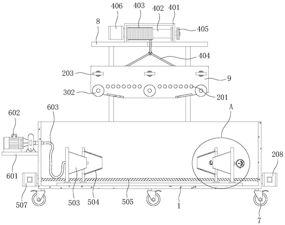
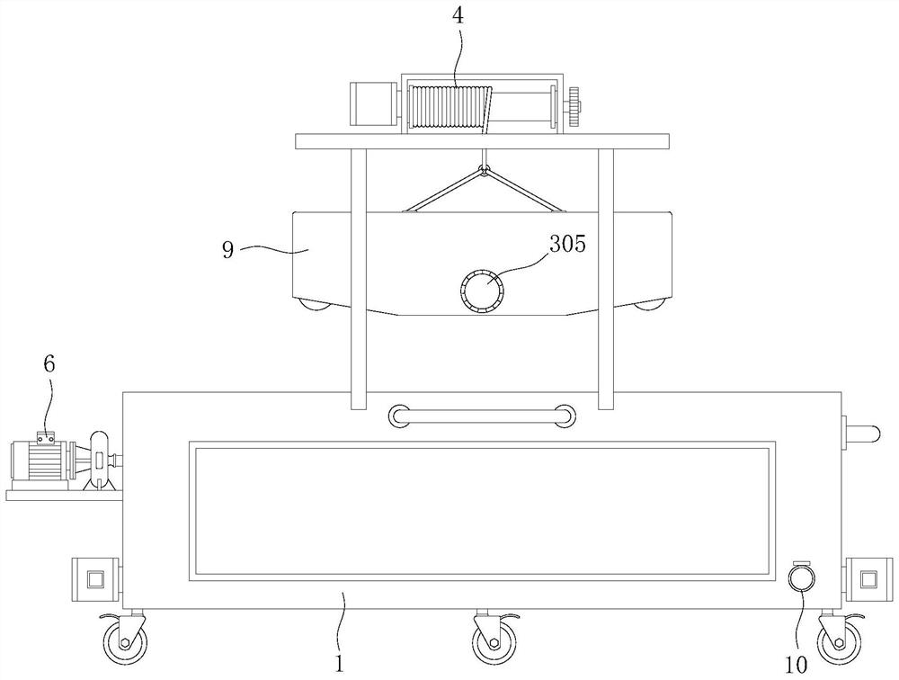
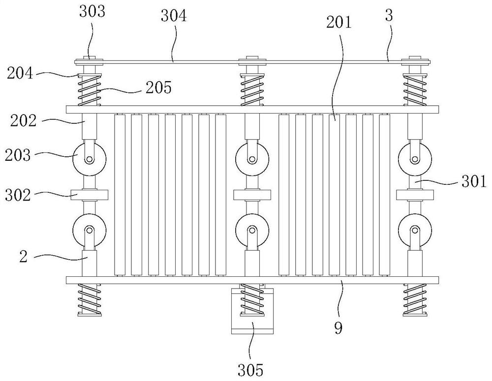
[0023] see Figure 1-5 , the present invention provides a technical solution: an automatic water testing device for pipeline processing, including a water testing tank 1, on which a transmission mechanism 2, a driving mechanism 3, a lifting mechanism 4, a sealing mechanism 5 and Pressure testing mechanism 6, six sets of brake wheels 7 are movable on the outer surface of the bottom of test water tank 1, support frame 8 is welded and installed on test water tank...


PUM


Abstract

The invention discloses an automatic water testing device for pipeline machining, and belongs to the technical field of pipeline machining. The automatic water testing device for pipeline machining comprises a water testing box; a transmission mechanism, a driving mechanism, a lifting mechanism, a sealing mechanism and a pressure testing mechanism are arranged on the water testing box; six sets ofbrake wheels are movably installed on the outer surface of the bottom of the water testing box; a supporting frame is installed on the water testing box in a welded mode; a trapezoidal frame is arranged in the supporting frame. The automatic water testing device for pipeline machining can automatically complete sealing operation on the interior of a steel pipe. Compared with a device for fixing and sealing the interior of the steel pipe through a blind plate, the device is simpler and more convenient to operate, does not need complex and difficult mounting and dismounting steps,relieves the labor burden of operators and improves production efficiency; Due to the conical structural design of a conical extrusion block and a conical rubber sealing cylinder, water testing operation can be conducted on steel pipes of different specifications, and the use scene and range of the device are widened.

Description

technical field [0001] The invention relates to the technical field of pipeline processing, in particular to an automatic water testing device for pipeline processing. Background technique [0002] After the steel pipe is produced, it needs to be tested for water testing, mainly for the sealing performance and pressure bearing capacity of the steel pipe. At present, most of the steel pipe water testing methods are to place the produced steel pipe on the fixed frame first, and then use the blind Temporarily seal the two ends of the steel pipe with the plate, and finally use the pressure test pump to inject water and pressurize the inside of the pipe to check whether its sealing performance and pressure capacity are qualified. Because the quality and volume of the steel pipe are large, it is inconvenient to move it. The operation of installing and removing the blind plates before and after is complicated and difficult, and the labor intensity of the operators is relatively hig...

Claims


Application Information

Patent Timeline
Patent Type & Authority Applications(China)
IPC IPC(8): G01M3/28G01N3/12
CPCG01M3/2815G01N3/12G01N2203/0019G01N2203/0048G01N2203/0274Y02A20/00
Inventor 邱波
Owner 湖南瑞邦管业有限公司
Learn More