Direct-current bias current detection device
A current detection device, DC bias technology, applied in measuring devices, using AC to DC for measurement, voltage/current isolation, etc., can solve problems such as transformer core saturation
- Summary
- Abstract
- Description
- Claims
- Application Information
AI Technical Summary
Problems solved by technology
Method used
Image

Examples
Embodiment 1
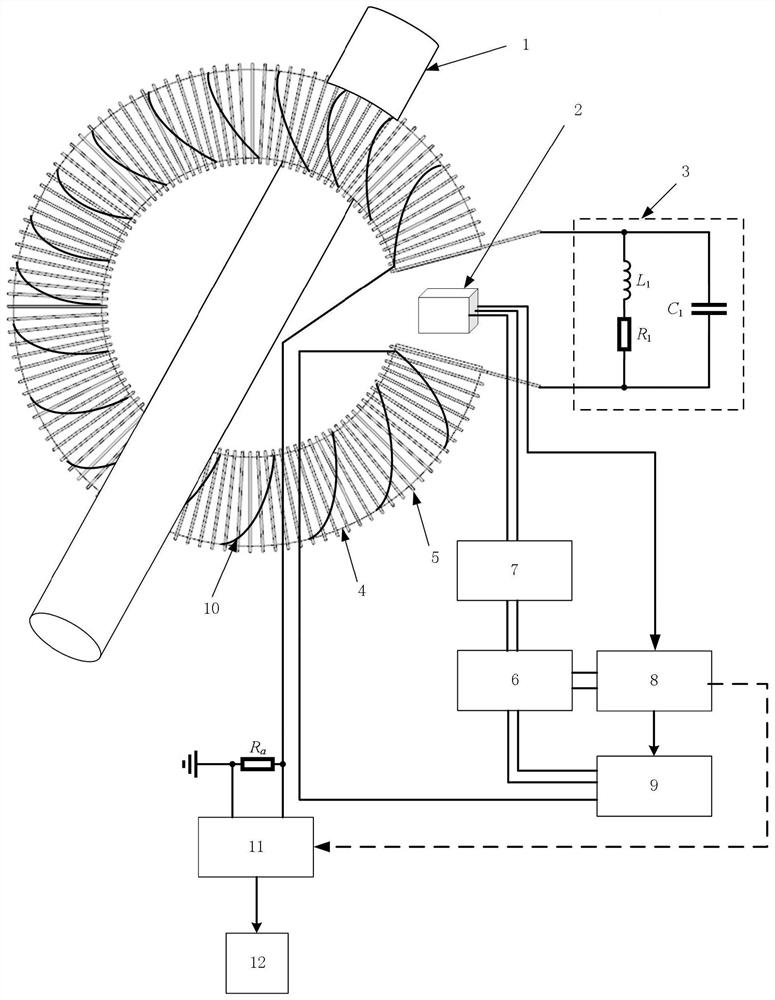
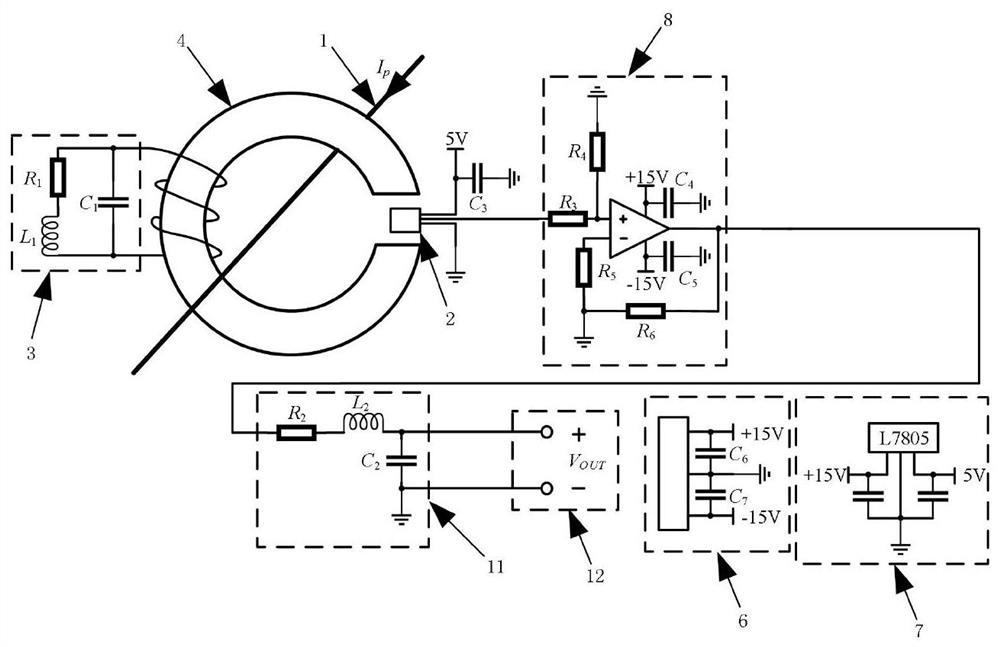
[0024] In order to further describe the direct detection method in the DC bias current detection device and its method, the following will be combined figure 1 and figure 2 Make a specific introduction. The device is composed of a Hall effect sensor 2, a low-loss damping circuit 3, a silicon steel annular opening magnetic ring 4, an AC magnetic flux cancellation coil 5, a power supply input terminal 6, a voltage conversion circuit 7, an operational amplifier 8, and a filter circuit 12.
[0025] The power supply input terminal 6 is a three-terminal base, the first terminal is connected to +15V power supply, the third terminal is connected to -15V power supply, and the second terminal is connected to the ground of +15V and -15V power supply, wherein the first terminal and the ground Parallel filter capacitor C 6 , between the third terminal and ground parallel filter capacitor C 7 ; The voltage conversion circuit 7 includes a linear voltage regulator, the input terminal of t...
Embodiment 2
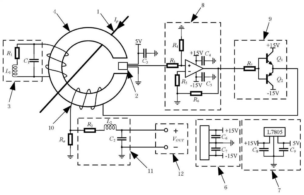
[0032] In order to further describe the indirect detection method in the DC bias current detection device and its method, the following is combined image 3 Make a specific introduction. The device consists of a Hall effect sensor 2, a low-loss damping circuit 3, a silicon steel annular opening magnetic ring 4, an AC magnetic flux cancellation coil 5, a power supply input terminal 6, a voltage conversion circuit 7, an operational amplifier 8, a power amplifier circuit 9, and a DC compensation The coil 10, the filter circuit 11, and the output terminal 12 are composed.
[0033] The power supply input terminal 6 is a three-terminal base, the first terminal is connected to +15V power supply, the third terminal is connected to -15V power supply, and the second terminal is connected to the ground of +15V and -15V power supply, wherein the first terminal and the ground Parallel filter capacitor C 6 , between the third terminal and ground parallel filter capacitor C 7 ; The voltag...
PUM
 Abstract
Description
Claims
Application Information
 - R&D
- Intellectual Property
- Life Sciences
- Materials
- Tech Scout
- Unparalleled Data Quality
- Higher Quality Content
- 60% Fewer Hallucinations
Browse by: Latest US Patents, China's latest patents, Technical Efficacy Thesaurus, Application Domain, Technology Topic, Popular Technical Reports.
© 2025 PatSnap. All rights reserved.Legal|Privacy policy|Modern Slavery Act Transparency Statement|Sitemap|About US| Contact US: help@patsnap.com