Artificial electromagnetic metamaterial-based ultra-wideband antenna for 5G communication

An ultra-broadband antenna and artificial electromagnetic technology, which is applied in the direction of antennas, antenna grounding devices, and devices that enable antennas to work in different bands at the same time, can solve the problems of underutilization of the same-phase reflection characteristics, unreasonable antenna structure design, and antenna bandwidth. Unsatisfactory characteristics and other problems, to achieve the effect of simple production and processing, easy to implement, and overcome narrow bandwidth

Pending Publication Date: 2021-02-12
HEFEI UNIV
View PDF21 Cites 0 Cited by
  • Summary
  • Abstract
  • Description
  • Claims
  • Application Information

AI Technical Summary

Problems solved by technology

[0003] In the prior art, without the use of artificial electromagnetic metamaterials, the distance between the radiator of the antenna and the antenna ground cannot reach the 0.85mm of this design, because the antenna ground completely reflects the electromagnetic waves in reverse. , and because of this reason, the bandwidth of the general antenna does not exceed 10%, which is the inherent narrowband characteristic of the planar microstrip antenna
On the other hand, even if the artificial electromagnetic metamaterial is applied to the antenna design, due to the unreasonable design of the antenna structure, for example, simply designing a strip-shaped dipole antenna placed on the artificial electromagnetic metamaterial, the artificial electromagnetic metamaterial The in-phase reflection characteristics of the material are not fully utilized, so the bandwidth characteristics of the antenna are not ideal, and even the bandwidth characteristics are very poor

Method used


Image

  • Artificial electromagnetic metamaterial-based ultra-wideband antenna for 5G communication
  • Artificial electromagnetic metamaterial-based ultra-wideband antenna for 5G communication
  • Artificial electromagnetic metamaterial-based ultra-wideband antenna for 5G communication

Examples


Embodiment 1

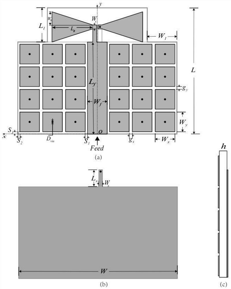
[0021] An ultra-wideband antenna based on artificial electromagnetic metamaterials for 5G communication, including a radiator and an artificial electromagnetic metamaterial, the ultra-wideband antenna is placed on the edge of the artificial electromagnetic metamaterial, and the upper layer of the radiator and the artificial electromagnetic metamaterial is pasted coplanar

[0022] The radiator is a dipole-type bow-tie antenna with broadband characteristics. The bow-tie antenna is composed of two arms, both arms are etched on the top surface of the dielectric substrate, and one of the arms is connected to the feed microstrip , while the other arm is connected to the ground wire on the lower surface of the dielectric substrate through metal vias. This structure is different from the traditional bow-tie antenna. Perhaps its two arms of the dipole antenna design of microstrip type are connected with the microstrip feed of upper strata and the antenna ground of lower floor respectiv...


PUM

PropertyMeasurementUnit
thicknessaaaaaaaaaa
relative permittivityaaaaaaaaaa
dielectric lossaaaaaaaaaa

Abstract

The invention discloses an artificial electromagnetic metamaterial-based ultra-wideband antenna for 5G communication. The artificial electromagnetic metamaterial-based ultra-wideband antenna comprisesa radiator and an artificial electromagnetic metamaterial; the ultra-wideband antenna is placed at the edge of the artificial electromagnetic metamaterial; the upper-layer patches of the radiator andthe artificial electromagnetic metamaterial are coplanar; the radiator is a dipole bow-tie antenna with broadband characteristics; the bow-tie antenna is composed of two arms; the two arms are located on the top surface of a dielectric substrate through etching; one of the arms is connected to a feed microstrip, and the other arm is connected to a ground wire on the lower surface of the dielectric substrate through a metal via hole; the artificial electromagnetic metamaterial is a mushroom-type artificial electromagnetic metamaterial; the structure of the artificial electromagnetic metamaterial is composed of an upper-layer metal patch, a middle dielectric substrate, a lower-layer grounding plane and a metal via hole for connecting the upper-layer metal patch to the lower-layer groundingplane. With the artificial electromagnetic metamaterial-basedultra-wideband antenna for 5G communication adopted, the defect that a traditional microstrip antenna is narrow in bandwidth is overcome.

Description

technical field [0001] The invention belongs to the technical field of communication equipment, and in particular relates to an ultra-wideband antenna based on artificial electromagnetic metamaterials for 5G communication. Background technique [0002] With the rapid development of modern wireless communication systems, the demand for wideband antennas is increasing. Despite the shortcomings of the narrow impedance bandwidth of microstrip antennas, microstrip patch antennas are becoming more and more prominent and widely used in today's military and civilian applications due to their small size, light weight and low cost. So far, many techniques have been reported to overcome the disadvantage of inherently narrow bandwidth, including the use of capacitive probe feeding, L-shaped probe feeding, slot coupling, U / E slot patch, and stacked patch, Typically less than 10% bandwidth broadening is obtained for the increase in inductance that comes with increasing probe length with ...

Claims


Application Information

Patent Timeline
Patent Type & Authority Applications(China)
IPC IPC(8): H01Q5/25H01Q1/38H01Q1/48
CPCH01Q5/25H01Q1/38H01Q1/48
Inventor 汪圣杰赵春江李翠花李祎
Owner HEFEI UNIV
Why Eureka
Try Eureka