Composite melt-blown fabric production device and composite melt-blown fabric production method

A technology of melt-blown cloth and cloth, which is applied to devices, coatings, textiles and paper making on the surface, which can solve the problems of troublesome cleaning, affecting the normal coating of cloth, and laborious operation.

Active Publication Date: 2021-02-19
福建智罗科技有限公司
View PDF7 Cites 3 Cited by
  • Summary
  • Abstract
  • Description
  • Claims
  • Application Information

AI Technical Summary

Problems solved by technology

The size (width) of the coating platform is usually fixed, so that when the cloth with a narrower width is knife-coated, since the width of the cloth is smaller than the width of the coating platform, the material liquid after scraping by the scraper will flow from The two sides of the scraper flow to both sides of the coating platform, and the coating liquid usually has a certain viscosity and curability. Therefore, the liquid flowing on both sides of the coating platform needs to be cleaned continuously, otherwise, the solidification On the coating platform, it will cause troublesome cleaning in the later stage and even affect the normal coating of the next piece of fabric
[0008] In addition, as the material feeding device of the main section of the coating process, since the feeding end of the feeding frame (unwinding frame) has a certain height, when feeding the fabric to the feeding frame, workers need to The fabric roll is lifted into the feeding station, and there is a technical problem of laborious operation
[0009] In summary, there is a need for improvement and further research in the process preparation and equipment optimization of the composite fabric production device in the prior art

Method used


Image

  • Composite melt-blown fabric production device and composite melt-blown fabric production method
  • Composite melt-blown fabric production device and composite melt-blown fabric production method
  • Composite melt-blown fabric production device and composite melt-blown fabric production method

Examples


Embodiment 1

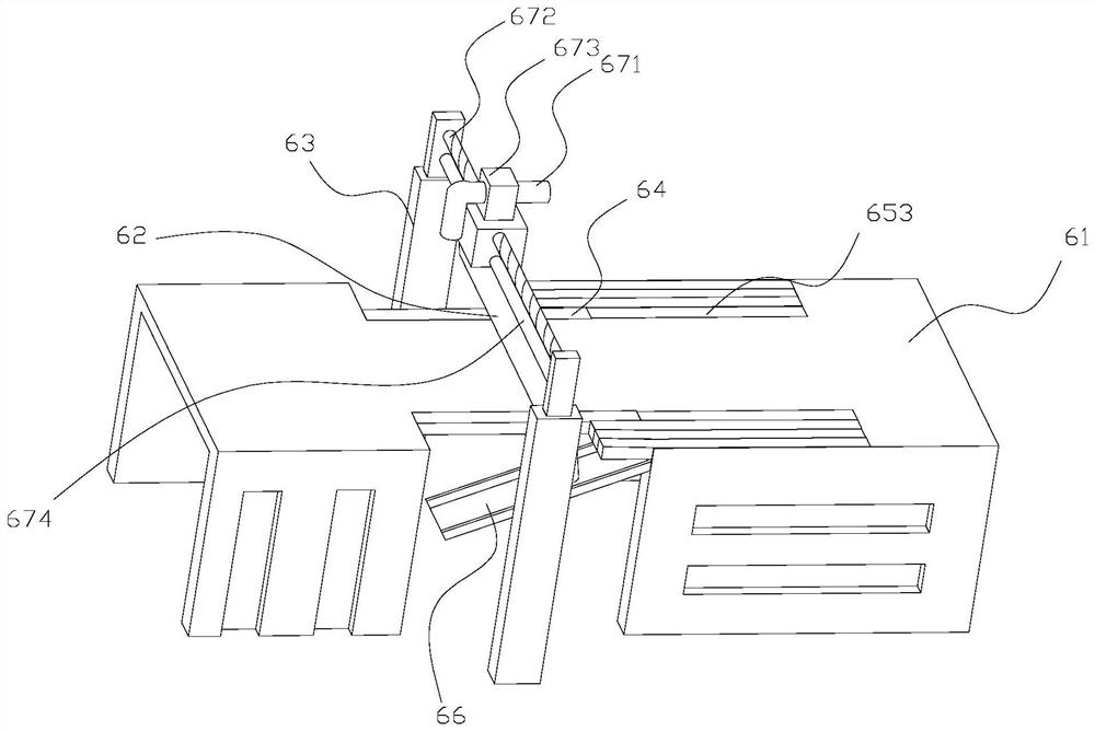
[0084] Such as Figure 1-4 As shown, this embodiment discloses a coating device, which includes a coating platform 61 and a scraper 62 . The scraper 62 is arranged above the coating platform 61, specifically on the coating platform support 63, there is a paint gap between the bottom of the scraper 62 and the top surface of the coating platform 61, and cloth can pass through the paint gap.

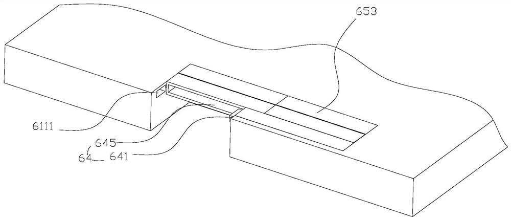
[0085] Notches 611 are symmetrically formed on both sides of the coating platform 61 in the width direction, and the projection of the scraper 62 in the vertical direction penetrates the notches 611 . At the rear end of the notch 611 is provided a placing groove with an opening upward. The placement slot communicates with the notch 611 and the inner sidewall of the placement slot is flush with the inner sidewall of the notch 611 . A support plate 613 is provided at the front end of the placement slot.

[0086] Such as figure 2 As shown, a mounting socket 6111 is opened on the front inn...

Embodiment 2

[0115] Such as Figure 9 As shown, this embodiment discloses a composite melt-blown fabric production device, which includes a feeding device 1, a coating device 6, a drying device 7, and a winding device 8 in sequence according to the process flow from front to back. Wherein, the drying device and the winding device are all prior art, and the drying device is preferably a tunnel oven. The coating device 6 is preferably the coating device of the above embodiment, and may also be other prior art.

[0116] The feeding device 1 is used to transport the cloth to the coating device 6, the coating device 6 is used to coat the cloth, the drying device 7 is used to dry the coated cloth, and the winding device 8 is used to Wind the dried fabric.

[0117] Such as Figure 10 , 11 As shown, the material loading and feeding device 1 includes an overturned material loading platform, a lifting platform 12 , and a fastening device 13 . The top of the flipping loading platform is a placem...

Embodiment 3

[0144] This embodiment discloses a production method of a composite melt-blown cloth, comprising the following steps:

[0145] Step 1. Feed the PP melt-blown cloth roll to the feeding device;

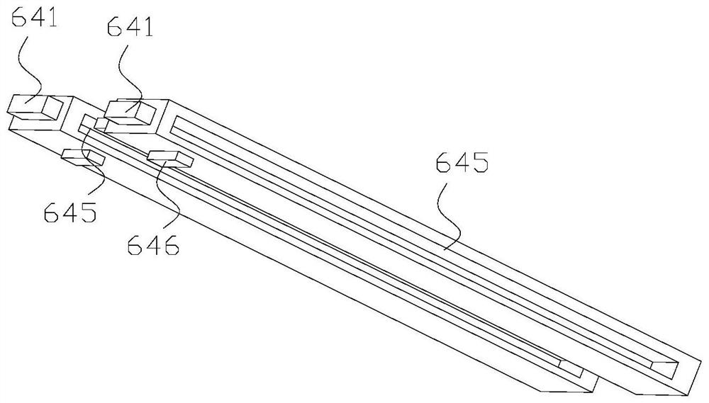
[0146] Step 2. Select the number of widened plates in each gap according to the width of the PP meltblown cloth, and move the outermost pair of widened plates in the selected widened plates in each gap until the selected widened plates are aligned Move forward to the installation mortise and mortise and mortise, and the corresponding cover plate is lifted and closed to adjust the width of the coating area;

[0147] Step 3, coating the PP melt-blown cloth;

[0148] Step 4, the coated PP melt-blown cloth is dried;

[0149] Step 5, the dried composite melt-blown fabric is wound and unloaded.

[0150]Step one includes the following steps:

[0151] S11. Turn the overturned feeding platform until the placement surface is an inclined surface where the end far away from the lifting platform...


PUM


Abstract

The invention discloses a coating device. A notch and a placing groove are formed in a coating platform; in the adjacent widening plates, a second long-strip open groove in the widening plate locatedinside is in sliding fit with a second long-strip convex block of the widening plate located outside, and a pushing convex block of the widening plate located outside extends into the long-strip guidegroove in the widening plate located inside to be in contact with the front inner wall of the long-strip guide groove; the widening plate located outside can move forwards to drive all the widening plates on the inner side of the widening plate to move forwards synchronously; and a cover plate can cover the placing groove, and the top surface of the cover plate is flush with the top surface of the coating platform. The invention further discloses a composite melt-blown fabric production device and a composite melt-blown fabric production method. The composite melt-blown fabric production device and the composite melt-blown fabric production method have the advantages that the coating breadth can be changed in real time to meet coating of cloth with different breadths, residues of coatingmaterials on the coating platform are reduced, the cloth function is improved, and the production efficiency is improved.

Description

technical field [0001] The invention relates to the technical field of melt-blown cloth, in particular to a production device for composite melt-blown cloth and a production method for composite melt-blown cloth. Background technique [0002] The melt-blown cloth uses high-speed hot air flow to draw the polymer melt stream extruded from the spinneret hole (discharge hole) of the die head, thereby forming ultra-fine fibers and collecting them on the condensing screen or roller, and at the same time Self-adhesive to become a melt-blown nonwoven fabric. [0003] With the development of society, people's demand for the performance of melt-blown cloth is no longer satisfied with the fiber material of melt-blown cloth itself, and various types of functionalized melt-blown cloth and preparation methods have emerged as the times require. [0004] The common functionalized or differentiated treatment of melt-blown cloth includes the method of lamination, and the lamination methods o...

Claims


Application Information

Patent Timeline
Patent Type & Authority Applications(China)
IPC IPC(8): B05C11/04B05C5/02B05C9/14B05C13/02D06N3/00D06N3/12
CPCB05C5/0245B05C9/14B05C11/048B05C13/02D06N3/00D06N3/0011D06N3/0038D06N3/0061D06N3/12
Inventor 陈文忠肖文峰
Owner 福建智罗科技有限公司
Why Eureka
Try Eureka