
Ball valve assembly device in manufacturing industry

An assembly device and manufacturing technology, applied in the direction of manufacturing tools, metal processing, metal processing equipment, etc., can solve the problems of low efficiency, low assembly speed, uneven assembly quality, etc., to improve assembly speed, improve efficiency, and ensure quality Effect

Pending Publication Date: 2021-02-19
邹福明
View PDF0 Cites 1 Cited by
  • Summary
  • Abstract
  • Description
  • Claims
  • Application Information

AI Technical Summary

Problems solved by technology

[0004] In order to overcome the shortcomings of low efficiency, uneven assembly quality, and low assembly speed, the technical problem is to provide a manufacturing ball valve assembly device that improves efficiency, uniform assembly quality, and high assembly efficiency

Method used


Image

  • Ball valve assembly device in manufacturing industry
  • Ball valve assembly device in manufacturing industry
  • Ball valve assembly device in manufacturing industry

Examples


Embodiment 1

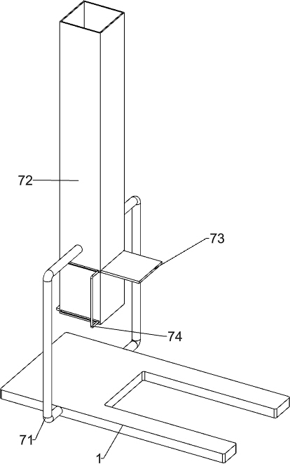
[0066] A manufacturing ball valve assembly device such as figure 1 As shown, it includes a base 1, a collection frame 2, a first bracket 3, a knocking mechanism 4, a moving mechanism 5, a discharging mechanism 6, and a blanking mechanism 7. A collection frame 2 is placed under the base 1, and the left side of the top of the base 1 The first bracket 3 is connected, the top of the first bracket 3 is connected with the knocking mechanism 4 between the top of the base 1, the moving mechanism 5 is connected between the base 1 and the knocking mechanism 4, and the rear right part of the base 1 is connected with a discharge mechanism 6. A blanking mechanism 7 is connected between the front and rear sides of the left part of the base 1.

[0067]When the staff needs to assemble the ball valve, the staff can first place the valve body in the unloading mechanism 7, place the ball valve in the discharging mechanism 6, start the knocking mechanism 4 to work, the knocking mechanism 4 moves ...

Embodiment 2

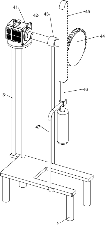
[0069] On the basis of Example 1, such as figure 2 As shown, the knocking mechanism 4 includes a motor 41, a rotating shaft 42, a bearing seat 43, missing teeth 44, a rack 45, a knocking rod 46 and a first sliding sleeve 47, and the top of the first bracket 3 is provided with a motor 41, and the base 1 The top rear side is provided with a bearing seat 43, the bearing seat 43 is rotatably connected with a rotating shaft 42, the left end of the rotating shaft 42 is connected with the output shaft of the motor 41, the right end of the rotating shaft 42 is connected with a missing tooth 44, and the front side of the top of the base 1 is connected with a first Sliding sleeve 47, the first sliding sleeve 47 is slidably connected with a knocking rod 46, the top of the knocking rod 46 is connected with a rack 45, and the rack 45 meshes with the missing tooth 44.

[0070] When the staff puts the ball valve in the discharge mechanism 6, the motor 41 starts to work, the motor 41 rotates...


PUM


Abstract

The invention relates to an assembly device, in particular to a ball valve assembly device in manufacturing industry. The ball valve assembly device in the manufacturing industry has the advantages that the efficiency is improved, the assembly quality is uniform, and the assembly speed is increased. The ball valve assembly device in the manufacturing industry comprises a base below which a collecting frame is arranged, a first bracket connected with one side of the top of the base, a knocking mechanism connected between the tops of the first bracket and the base, and a moving mechanism connected between the base and the knocking mechanism. Through cooperation of a motor, a rotating shaft, missing teeth and a knocking rod, the purpose of assembling a ball valve is achieved, and the efficiency is improved; through cooperation of a transmission assembly, a roller, a mounting plate and a rotating block, the purpose of automatic operation is achieved; and the assembly speed is increased.

Description

technical field [0001] The invention relates to an assembly device, in particular to an assembly device for a manufacturing ball valve. Background technique [0002] With the development of the times, more and more valves are used, and the valve manufacturing industry has achieved unprecedented development. my country's valve manufacturing industry, after long-term development, has become more and more specialized, including ball valves, high-pressure valves, explosion-proof valves, regulating valves, pressure reducing valves, etc. The technological content is getting higher and higher, and the competition is becoming more intense. [0003] In my country's ball valve production enterprises, most of the ball valve production enterprises use the assembly line to manually assemble the ball valve. The traditional ball valve assembly process is: the staff holds the valve body, then places the ball valve on the valve body, and then the staff holds the hand to knock Striking the co...

Claims


Application Information

Patent Timeline
Patent Type & Authority Applications(China)
IPC IPC(8): B23P19/02
CPCB23P19/02
Inventor 邹福明
Owner 邹福明
Learn More