
Automatic feeding and discharging viscoelastic bar machining device

A technology of automatic loading and unloading and processing equipment, which is applied in the direction of metal processing equipment, metal processing machinery parts, manufacturing tools, etc., and can solve problems such as sticking together without separation, sticking, and drilling difficulties

Active Publication Date: 2021-02-19
HUBEI UNIV OF TECH
View PDF10 Cites 4 Cited by
  • Summary
  • Abstract
  • Description
  • Claims
  • Application Information

AI Technical Summary

Problems solved by technology

When cutting viscous and elastic rod-shaped materials, due to the particularity of the material, it is often prone to deformation of the rod during the cutting process. There are problems such as sticking to the workbench or cutter, and there is a lack of devices that can separately complete the end cutting of multiple sections of bars with similar length and size requirements. Currently, the above problems can be solved on the market, and these viscous and elastic bars can be processed quickly, efficiently and with high precision. Devices for end-cutting material do not yet exist
In addition, when drilling viscoelastic rods, there are also drilling difficulties, and the required aperture cannot be accurately obtained, which easily leads to deformation of the material during processing. There is no such thing as an automatic production line for end cutting and punching of viscoelastic materials.

Method used


Image

  • Automatic feeding and discharging viscoelastic bar machining device
  • Automatic feeding and discharging viscoelastic bar machining device
  • Automatic feeding and discharging viscoelastic bar machining device

Examples


Embodiment Construction

[0068] Embodiments of the present invention will be further described in detail below in conjunction with the accompanying drawings and examples. The following examples are used to illustrate the present invention, but should not be used to limit the scope of the present invention.

[0069] The preferred embodiments of the present invention will be described in detail below in conjunction with the accompanying drawings, so that the advantages and features of the present invention can be more easily understood by those skilled in the art, so as to define the protection scope of the present invention more clearly.

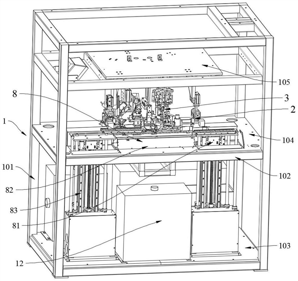
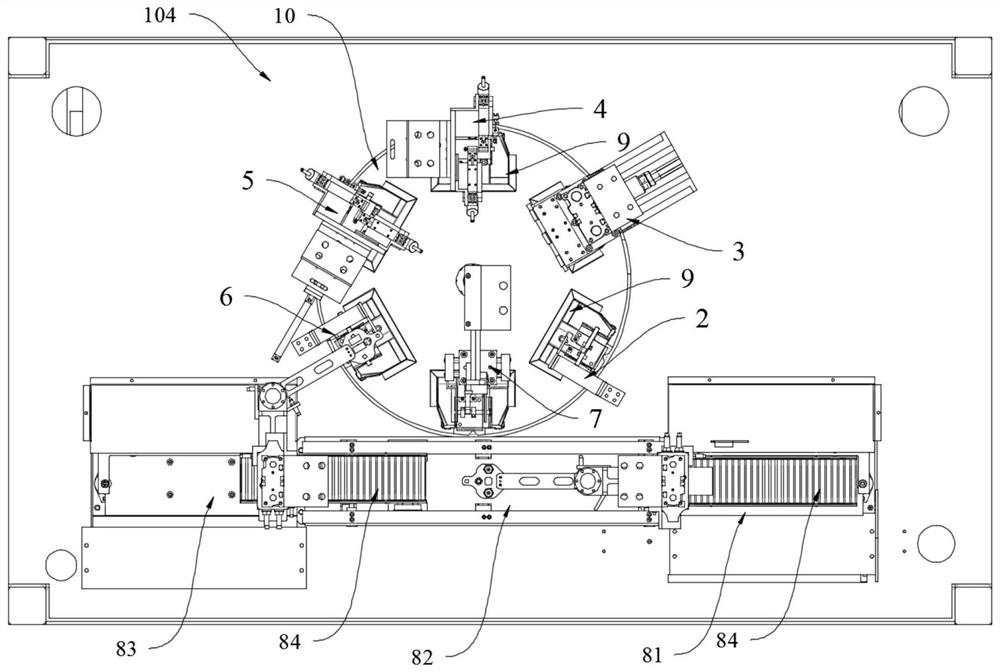
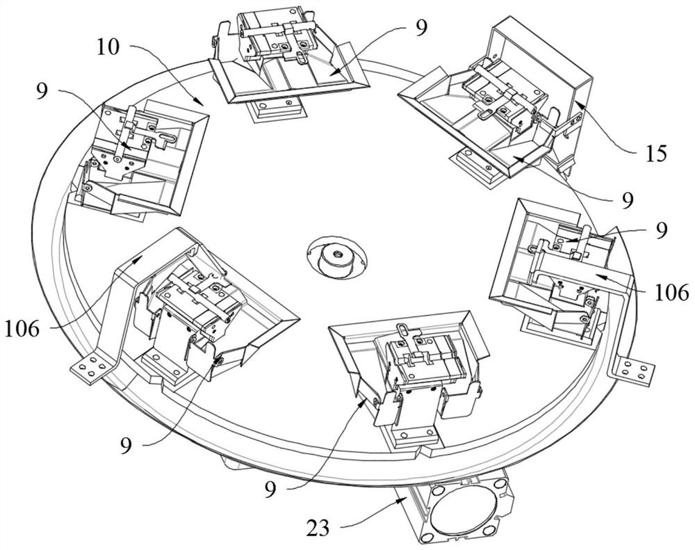
[0070] Such as Figure 1 to Figure 27As shown, a viscoelastic bar processing device with automatic loading and unloading includes a frame 1 and a feeding device 2 installed on the frame 1, an end cutting device 3, a punching device 4, a hole cleaning device 5, and a blanking device. Device 6, waste cleaning device 7, material conveying device 8 and turntable 10. The...


PUM


Abstract

The invention discloses an automatic feeding and discharging viscoelastic bar machining device. The automatic feeding and discharging viscoelastic bar machining device comprises a machine frame and further comprises a feeding device, an end cutting device, a punching device, a hole cleaning device, a discharging device, a waste sweeping device, a material conveying device and a machining platformwhich are installed on the machine frame. The machining platform comprises a rotation disc and a work platform, the rotation disc is installed in a round hole in the middle of the work platform, the feeding device, the end cutting device, the punching device, the hole cleaning device, the discharging device and the waste sweeping device are sequentially installed on the periphery of the rotation disc at equal intervals to form six stations including the feeding station, the end cutting station, the punching station, the hole cleaning station, the discharging station and the sweeping station, and six viscoelastic bar clamping devices corresponding to the six stations are arranged on the rotation disc. The material conveying device is used for conveying material discs along a fixed path; andin the rotating process of the rotation disc, the six stations conduct corresponding action machining, and automatic machining of viscoelastic bar-shaped materials is achieved. The automatic feedingand discharging viscoelastic bar machining device is high in machining efficiency and precision and capable of achieving automatic operation.

Description

technical field [0001] The invention belongs to the field of material processing, and relates to a material cutting and processing technology, in particular to a viscoelastic rod processing device for automatic loading and unloading. Background technique [0002] Viscous and elastic rod-shaped materials are referred to as viscoelastic materials, which are widely used in aerospace, chemical, mining, medical and many other industries. When cutting viscous and elastic rod-shaped materials, due to the particularity of the material, it is often prone to deformation of the rod during the cutting process. There are problems such as sticking to the workbench or cutter, and there is a lack of devices that can separately complete the end cutting of multiple sections of bars with similar length and size requirements. Currently, the above problems can be solved on the market, and these viscous and elastic bars can be processed quickly, efficiently and with high precision. Devices for e...

Claims


Application Information

Patent Timeline
IPC IPC(8): B23P23/06B23Q11/00
CPCB23P23/06B23Q11/0067
Inventor 张铮胡凌辉王蕾雷勇高博超常步苏旭武熊盛辉王孙强王欣姚亚健
Owner HUBEI UNIV OF TECH
Learn More