Coal mine underground gangue in-situ separation and in-situ grouting filling method

A gangue and sorting technology, which is applied in filling materials, chemical instruments and methods, solid separation, etc., can solve problems that cannot be widely used, threats to the ecological environment, low filling efficiency, etc., and achieve reduced surface subsidence, large filling capacity, The effect of increasing lift

Active Publication Date: 2021-02-19
中煤能源研究院有限责任公司 +1
View PDF5 Cites 5 Cited by
  • Summary
  • Abstract
  • Description
  • Claims
  • Application Information

AI Technical Summary

Problems solved by technology

[0002] During the construction and production of underground coal mines, a large amount of solid waste—coal gangue will be generated, which will be lifted to the ground for stacking. The traditional treatment method is Continue to stack coal gangue on the surface or carry out comprehensive utilization. Comprehensive utilization adheres to the concept of green development, so that coal gangue can be used in many aspects such as power generation, building materials, fertilizer making and reclamation, but it can only solve a small part of coal gangue, and there are still A large amount of coal gangue is piled on the surface, forming a unique gangue hill in coal mines, which poses a great threat and damage to the ecological environment
In recent years, with the rapid development of underground filling in coal mines, filling coal gangue as solid or paste material in gobs has become an effective way to solve the problem of coal gangue efflux, but for solid filling, its filling efficiency is low and high filling cost have become the main factors restricting its development, while the high cost and complicated process of paste filling prevent it from being widely used

Method used


Image

  • Coal mine underground gangue in-situ separation and in-situ grouting filling method
  • Coal mine underground gangue in-situ separation and in-situ grouting filling method
  • Coal mine underground gangue in-situ separation and in-situ grouting filling method

Examples


Embodiment Construction

[0026] For better understanding of the present invention, the present invention will be further described below with reference to the accompanying drawings and embodiments.

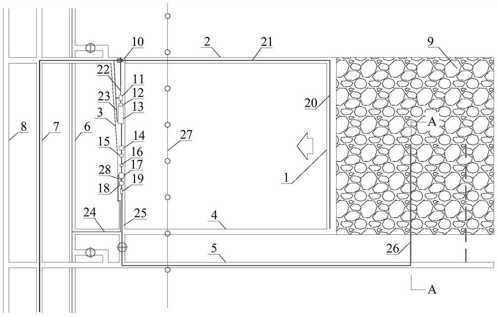
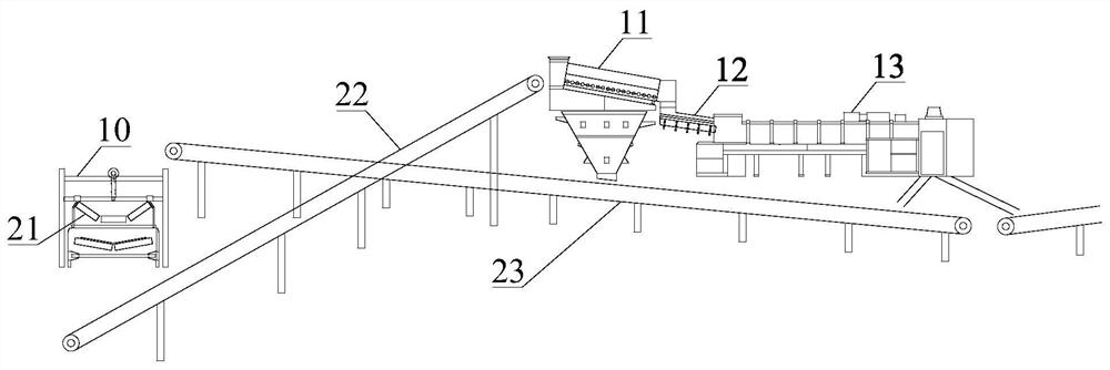
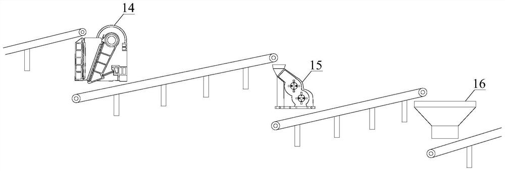
[0027] like Figure 1 to Figure 5 As shown in the figure, the present invention provides a method for in-situ grouting and filling of coal mine gangue in situ sorting. The method first uses a plow unloader 10 to transfer the raw coal on the coal transport belt 21 in the transport lane to the sorting and pulping. Then, the raw coal is divided into clean coal, fine coal and gangue by the screening and sorting system. The clean coal and fine coal are returned to the coal conveying belt 21 in the transport lane through the coal return belt 23, and the gangue passes through the crushing system and the pulping system. It is made into a slurry with a preset concentration, and finally, the gangue slurry is transported by the grouting pump 19 through the grouting pipe 25 through the transportation lane 5 of the ad...


PUM


Abstract

The invention discloses a coal mine underground gangue in-situ separation and in-situ grouting filling method. The coal mine underground gangue in-situ separation and in-situ grouting filling method comprises the following steps that firstly, raw coal on a coal conveying belt in a conveying roadway is transferred to a separation slurrying roadway by utilizing a plow discharger; then the raw coal is divided into clean coal, fine coal and gangue through a screening and separation system, the clean coal and the fine coal are returned to the coal conveying belt in the conveying roadway through a coal return belt, and the gangue is made into slurry with preset concentration through a crushing system and a slurrying system; and finally, gangue slurry is conveyed by a grouting pump through a pipeline to pass through the conveying roadway and the adjacent grouting hole of the adjacent working face to fill a goaf behind the stope working face. Under the condition that normal production of a coal mine is not affected, the coal gangue does not ascend, and the in-situ goaf can be filled with the coal gangue efficiently and safely with low cost.

Description

technical field [0001] The invention belongs to the technical field of mining, and in particular relates to a method for in-situ grouting and filling of gangue in underground coal mines, which is suitable for coal mining working faces with more gangue in coal seams and little water inflow. Background technique [0002] During the construction and production process of underground coal mines, a large amount of solid waste, coal gangue, will be generated, and it will be lifted to the ground for stacking. With the concept of green development, coal gangue is used in power generation, building materials, fertilizer production and reclamation, etc. However, it can only solve a small amount of coal gangue, and a large amount of coal gangue is still piled on the surface, forming a coal mine-specific gangue mountain. The ecological environment has caused great threat and damage. In recent years, with the rapid development of underground filling in coal mines, filling coal gangue as...

Claims


Application Information

Patent Timeline
Patent Type & Authority Applications(China)
IPC IPC(8): E21F15/00B02C21/00B07B1/28
CPCE21F15/005B02C21/00B07B1/28
Inventor 申斌学朱磊潘浩刘成勇张新福刘治成古文哲徐凯吴玉意李娟秋丰岐宋天奇程海星刘文涛黄剑斌赵萌烨袁超峰孙俊彦
Owner 中煤能源研究院有限责任公司
Why Eureka
Try Eureka