Failure tester for electric power cable

A technology of power cables and testers, applied in fault locations, electromagnetic wave detection, instruments, etc., can solve the problems of large influence of power frequency interference, and achieve the effect of convenient on-site use

Inactive Publication Date: 2003-10-08
CHINA PETROLEUM & CHEM CORP +1
View PDF1 Cites 2 Cited by
  • Summary
  • Abstract
  • Description
  • Claims
  • Application Information

AI Technical Summary

Problems solved by technology

This method can only measure the fault of the grounding cable, and is greatly affected by power frequency interference. At the same time, the fault point must be determined under the condition of known cable direction

Method used


Image

  • Failure tester for electric power cable
  • Failure tester for electric power cable
  • Failure tester for electric power cable

Examples


Embodiment Construction

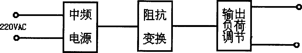
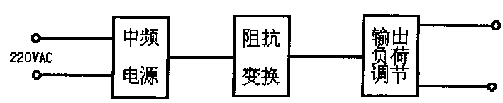
[0009] Further description below in conjunction with accompanying drawings. The intermediate frequency transmission part of the power cable fault tester of the present invention changes the 220VAC power supply into an intermediate frequency power supply, and the intermediate frequency power supply can use an intermediate frequency generator whose frequency can be fixed at 800HZ, and the output of the intermediate frequency generator is connected to an impedance transformation circuit. The circuit itself is an impedance transformation transformer, on the one hand, the output of the transformer is reduced to 36VAC, and on the other hand, its load characteristics are improved. After being regulated by the output load regulator, it can be directly connected to the cable under test. If you measure the direction of the fault-free cable, the other end of the cable will be short-circuited with the two cores connected to the output of the impedance transformation circuit. If it is to ...


PUM


Abstract

A failure test of electric power cable is composed of signal transmitter and signal receiver. Said signal transmitter consists of a MF power supply (220 V AC), impedance converter for converting 220 V at 800 Hz to 36V AC at 800 Hz, and load regulator for outputting. Said signal receiver is a low-frequency one. Its advantages include simple structure, convenient application, and small size.

Description

technical field [0001] The invention relates to a power cable fault tester, in particular to a tester for underground power cables. It can test the power cables of industrial and mining enterprises, including the laying direction of power cables laid underground and the fault points of short circuit and grounding faults. Background technique [0002] The direction of the existing power cables is searched by the archives accumulated over the years and the memories of old workers and technicians. There are many large factories and old factories with incomplete files. No one knows the direction of some cables after the old workers retire. It brings difficulties to power system transformation and other construction, especially when the cable fails, because the exact location of the fault is not known, it can only be excavated after a rough survey, and often the fault location cannot be found after digging a large area. [0003] Chinese patent CN93103937 proposes a method for ...

Claims


Application Information

Patent Timeline
Patent Type & Authority Patents(China)
IPC IPC(8): G01R31/02G01R31/08G01V3/12
Inventor 张金玺谭万方潘荣双
Owner CHINA PETROLEUM & CHEM CORP
Why Eureka
Try Eureka