General calibration method for phase retardation error of snapshot-type Mueller matrix ellipsometer
A technology of Mueller matrix and phase delay, which is applied in the field of general calibration of phase delay error of snapshot Mueller matrix ellipsometer, can solve problems such as difficulty in applying phase delay, inconsistency of actual conditions, and error of calibration results, etc., to achieve good results Effects of error calibration results, improvement of measurement accuracy, and exclusion of edge effects
- Summary
- Abstract
- Description
- Claims
- Application Information
AI Technical Summary
Problems solved by technology
Method used
Image

Examples
Embodiment 1
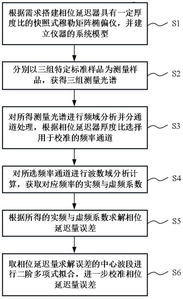
[0055] Taking the measurement configuration with a phase retarder thickness ratio of 1:1:5:5 as an example, the phase retardation calibration method of the present invention is introduced, including the following steps:
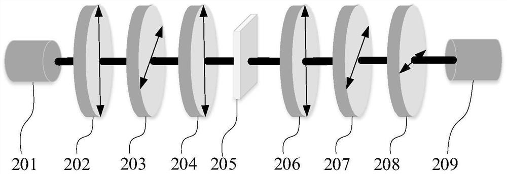
[0056] S1. First establish the measurement model of the snapshot Mueller matrix ellipsometer: take the azimuth angle of the polarizer 201 as a reference, and set the azimuth angle α of the analyzer 208 2 =90°, phase retarder-203 azimuth angle θ 1 =45°, phase retarder two 204 azimuth angle θ 2 =0°, phase retarder three 206 azimuth angle θ 3 =0°, phase retarder four 207 azimuth angle θ 4 = 45°; for a measurement configuration with a thickness ratio of 1:1:5:5, there is d 1 = d 2 = 1, d 3 = d 4 = 5; then the model of the system can be expressed as:
[0057] S out =P 2 (90)R 4 (45,δ 4 )R 3 (0,δ 3 )MR 2 (0,δ 2 )R 1 (45,δ 1 )P 1 (0)S in (5)
[0058] Among them, S in with S out Respectively represent the Stokes vectors of the light emitted by ...
Embodiment 2
[0116] In order to further illustrate the versatility of the snapshot-type Mueller matrix ellipsometer phase delay error calibration method of the present invention, that is, it is applicable to any thickness ratio configuration that can solve the full Mueller matrix, another group of specific implementations is given here For example, a measurement configuration with a phase retarder thickness ratio of 1:4:2:9.
[0117] In view of the measurement configurations with different thickness ratios, the basic model of the measurement system and the basic process of phase delay calibration have not changed. Therefore, in this embodiment, the processing and calculation process of each step is not given in detail, and only the calculation process due to the thickness ratio is given. different selection results.
[0118] In step S1, its thickness ratio is changed to d 1 = 1, d 2 = 4, d 3 = 2,d 4 =9; the highest modulation frequency mo of the system is mo=1+4+2+9=16;
[0119] For t...
PUM
| Property | Measurement | Unit |
|---|---|---|
| thickness | aaaaa | aaaaa |
| width | aaaaa | aaaaa |
| angle of incidence | aaaaa | aaaaa |
Abstract
Description
Claims
Application Information
 - R&D
- Intellectual Property
- Life Sciences
- Materials
- Tech Scout
- Unparalleled Data Quality
- Higher Quality Content
- 60% Fewer Hallucinations
Browse by: Latest US Patents, China's latest patents, Technical Efficacy Thesaurus, Application Domain, Technology Topic, Popular Technical Reports.
© 2025 PatSnap. All rights reserved.Legal|Privacy policy|Modern Slavery Act Transparency Statement|Sitemap|About US| Contact US: help@patsnap.com