Expandable thin film light shield
A sunshade and deployable technology, which is applied in the field of sunshade, can solve the problems of complex inflation system, insufficient rigidity, and heavy weight of the sunshade, and achieve the effect of simple and reliable driving mode, satisfying shading and shape dimension, and light weight
- Summary
- Abstract
- Description
- Claims
- Application Information
AI Technical Summary
Problems solved by technology
Method used
Image
Examples
Embodiment 1
[0040] This embodiment provides a light-weight, large storage ratio, and large-scale expandable film shading cover with high rigidity in the unfolded state. When folded, the shading cover is pressed against the bottom frame, and after unfolding, it forms a diagonally cut polygonal body structure, which is suitable for Space optics satellite.
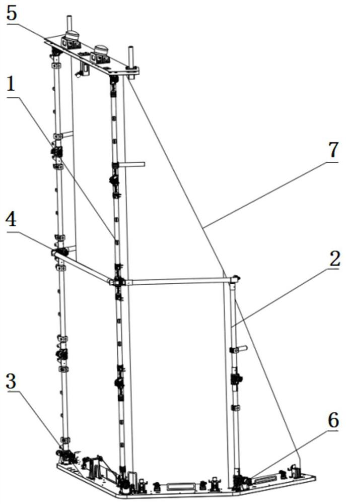
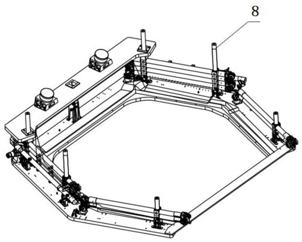
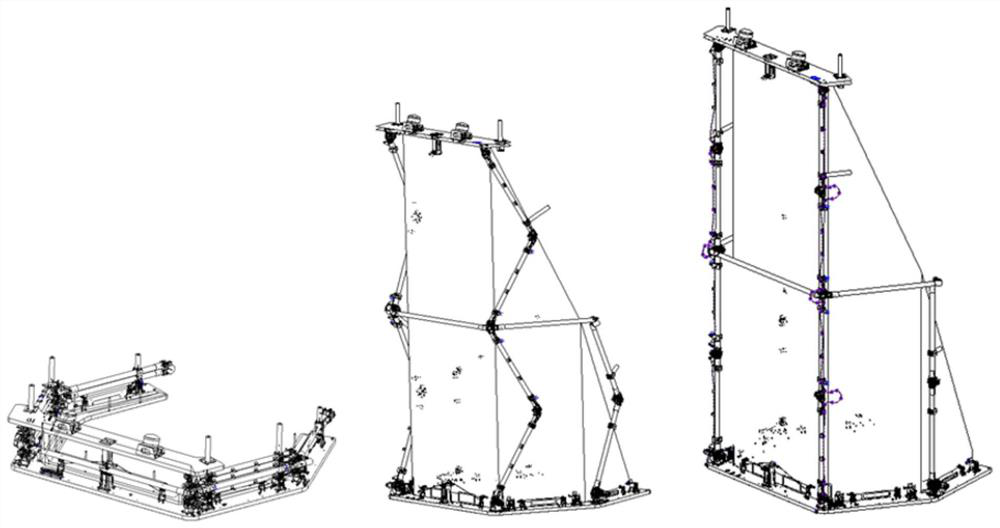
[0041] Such as Figure 1-Figure 3 As shown, the shading cover includes: an expandable skeleton, a light-shielding film 7 and a compression release device 8; wherein the expandable skeleton is used as the main support structure of the shading cover, which is directly related to the position accuracy, profile accuracy and basic structure of the shading cover after deployment. Frequency; the expandable skeleton includes: two sets of large connecting rod expansion mechanisms 1, two sets of small connecting rod expansion mechanisms 2, bottom frame 3, middle frame 4, upper frame 5 and linkage device 6; figure 1 In the unfolded state of the ho...
Embodiment 2
[0056] On the basis of Embodiment 1 above, the structure of the compression release device is further described in detail.
[0057] Such as Figure 7 It is a schematic diagram of compression state and release state of compression release device. The compression release device includes: a separation nut 16, a compression rod 17 and a separation spring 18; wherein the separation nut 16 is a pyrotechnic separation nut, which is fixed inside the compression seat by four screws, and the compression seat is arranged on the bottom frame 3; The position corresponding to the compression seat on the middle bulkhead frame 4 and the upper bulkhead frame 5 is provided with a mounting hole for the compression rod 17 to pass through; Screw and pre-tighten the threads of the separation nut 16. At this time, the compression rod 17 compresses the expandable skeleton. The separation spring 18 is set outside the compression rod 17. One end is in conflict with the frame 5, and the other end is co...
Embodiment 3
[0061] On the basis of the above-mentioned embodiment 1 or embodiment 2, the linkage sheave adopts a built-in design to avoid the extra lateral bending moment caused by the hinge due to the external linkage sheave; at the same time, the linkage rope adopts internal routing accordingly, through a The linkage rope is introduced into the inside of the connecting rod to the guide wheel (that is, the connecting rod adopts a hollow rod, and the linkage sheave is arranged inside the connecting rod, and correspondingly, the linkage rope is routed from the inside of the connecting rod). Compared with the external wiring, this wiring method can effectively eliminate the risk of the linkage rope being caught with other parts during the movement.
PUM
 Abstract
Description
Claims
Application Information
 - R&D
- Intellectual Property
- Life Sciences
- Materials
- Tech Scout
- Unparalleled Data Quality
- Higher Quality Content
- 60% Fewer Hallucinations
Browse by: Latest US Patents, China's latest patents, Technical Efficacy Thesaurus, Application Domain, Technology Topic, Popular Technical Reports.
© 2025 PatSnap. All rights reserved.Legal|Privacy policy|Modern Slavery Act Transparency Statement|Sitemap|About US| Contact US: help@patsnap.com


