
Mounting machine for chip processing

A placement machine and chip technology, applied in the direction of electrical components, semiconductor/solid-state device manufacturing, circuits, etc., can solve the problems of reduced bonding force between chips and substrates, easy adsorption of other impurities by glue, and inability to handle glue well, etc. Achieve the effects of improving aesthetics, good mounting effect, and convenient drying process

Inactive Publication Date: 2021-02-19
郝建兵
View PDF0 Cites 3 Cited by
  • Summary
  • Abstract
  • Description
  • Claims
  • Application Information

AI Technical Summary

Problems solved by technology

[0003] When crimping the chip, if there is too much glue between the chip and the substrate, the glue will overflow from between the chip and the motherboard, and the overflowing glue will easily absorb other impurities, which may cause short circuit and damage to the chip. If there is too little glue, Then the bonding force between the chip and the substrate is reduced, and even poor electrical connection occurs, which affects the high-speed operation of the chip. In the actual operation process, it is difficult to control the amount of glue. To deal with the overflowing glue well, for this reason, we propose a placement machine for chip processing

Method used


Image

  • Mounting machine for chip processing
  • Mounting machine for chip processing
  • Mounting machine for chip processing

Examples


Embodiment Construction

[0023] The following will clearly and completely describe the technical solutions in the embodiments of the present invention with reference to the accompanying drawings in the embodiments of the present invention. Obviously, the described embodiments are only some, not all, embodiments of the present invention. Based on the embodiments of the present invention, all other embodiments obtained by persons of ordinary skill in the art without making creative efforts belong to the protection scope of the present invention.

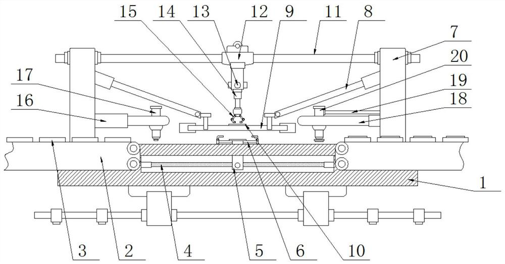
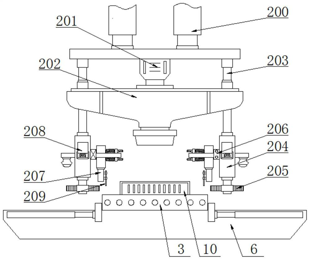
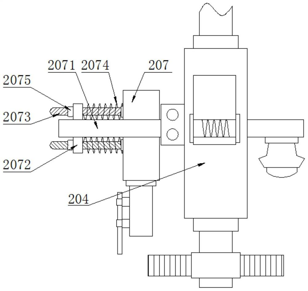
[0024] see Figure 1~4 , a placement machine for chip processing, comprising a base 1, transfer guide rails 2 are arranged on both sides of the top of the base 1, a main board 3 is placed on the left transfer guide rail 2, a horizontal groove is opened in the base 1, and wires are arranged in the base 1. The rod 4 and the screw rod 4 slide and socket the screw rod slider 5. The screw rod slider 5 passes through the base 1 and connects with the base plate 6. Th...


PUM


Abstract

The invention discloses a mounting machine for chip processing in the technical field of chip processing and production, which comprises a base, conveying guide rails arranged on the two sides of thetop end of the base, a horizontal groove formed in the base, a screw rod arranged in the horizontal groove, a screw rod sliding block slidably sleeving the screw rod, and stand columns arranged on thetwo sides of the top end of the base, wherein thescrew rod sliding block penetrates through the base and a substrate, the stand columns are connected with push rods, a supporting plate is arranged between the two sets of pull rods, a front-back guide rail is arranged on the supporting plate, a chip is placed on the front-back guide rail, a transverse rod is arranged between the top ends of the two sets of stand columns, a fixing base is arranged in the middle of the transverse rod, and the bottom end of the fixing base is connected with a front-back guide rod which is sleeved with a front-back sliding block in a sliding mode. The bottom end of the front-back sliding block is connected with a clamping block through a connecting rod, the left side stand column is connected with a left supporting rod, a glue dripping barrel is arranged on the left supporting rod, the right side stand column is connected with a right supporting rod, and the right supporting rod is slidably sleeved with acrimping device, so that overflowing glue can be effectively utilized during mounting, the mounting attractiveness is enhanced, and the mounting quality is improved.

Description

technical field [0001] The invention relates to the technical field of chip processing and production, in particular to a placement machine for chip processing. Background technique [0002] Chip mounting is a very critical step in the packaging process. Its main purpose is to grab a single chip from the cut wafer, place it on the corresponding position of the motherboard, and use glue to bond the chip and the motherboard. , the main process can be subdivided into three steps: dispensing glue, taking chips, and patching. Among them, the glue is generally formed by mixing epoxy resin, silver powder and additives, epoxy resin provides adhesion, and silver powder plays a conductive role; [0003] When crimping the chip, if there is too much glue between the chip and the substrate, the glue will overflow from between the chip and the motherboard, and the overflowing glue will easily absorb other impurities, which may cause short circuit and damage to the chip. If there is too li...

Claims


Application Information

Patent Timeline
Patent Type & Authority Applications(China)
IPC IPC(8): H01L21/67
CPCH01L21/67144
Inventor 郝建兵
Owner 郝建兵
Learn More