A connector terminal punching machine

A connector terminal and machine tool technology, which is applied in the field of punching machines, can solve the problems of low feeding efficiency, and achieve the effects of timely and accurate adjustment of feeding and reducing floor space.

Active Publication Date: 2022-02-22
乐清市嘉得电子有限公司
View PDF13 Cites 0 Cited by
  • Summary
  • Abstract
  • Description
  • Claims
  • Application Information

AI Technical Summary

Problems solved by technology

[0005] In order to improve the problem of low feeding efficiency, the application provides a connector terminal punching machine

Method used


Image

  • A connector terminal punching machine
  • A connector terminal punching machine
  • A connector terminal punching machine

Examples


Embodiment Construction

[0034] The following is attached Figure 1-6 The application is described in further detail.

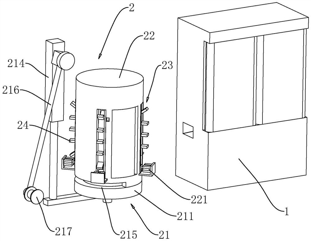
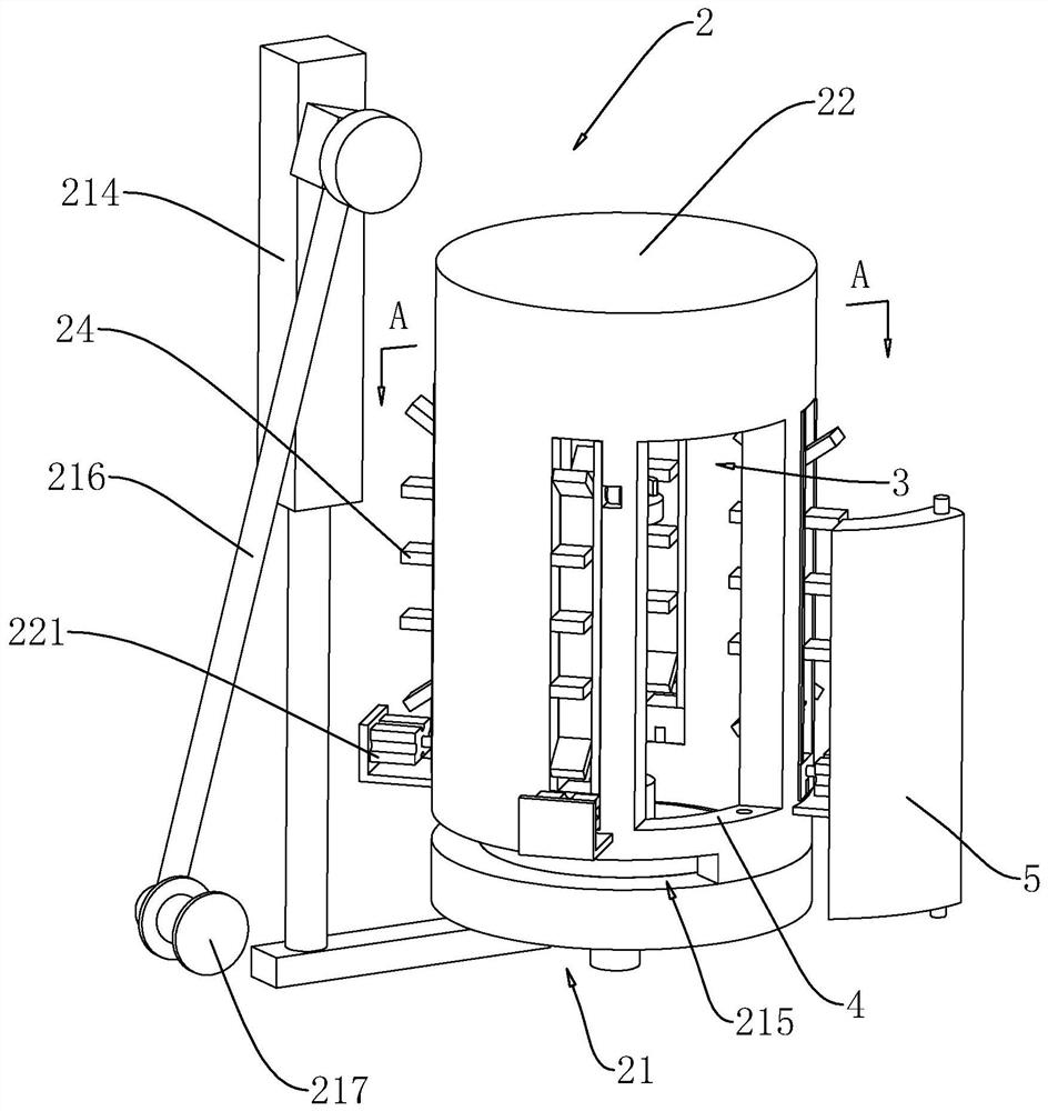
[0035] The embodiment of the present application discloses a connector terminal punching machine. refer to figure 1 , figure 2 , The connector terminal punch machine includes a punch body 1, and a feeding device 2 for feeding copper strips to the feed port of the punch body 1 is placed on one side of the punch body 1. The feeding device 2 includes a support base 21 located at the bottom, and a feeding base 22 arranged above the support base 21 .

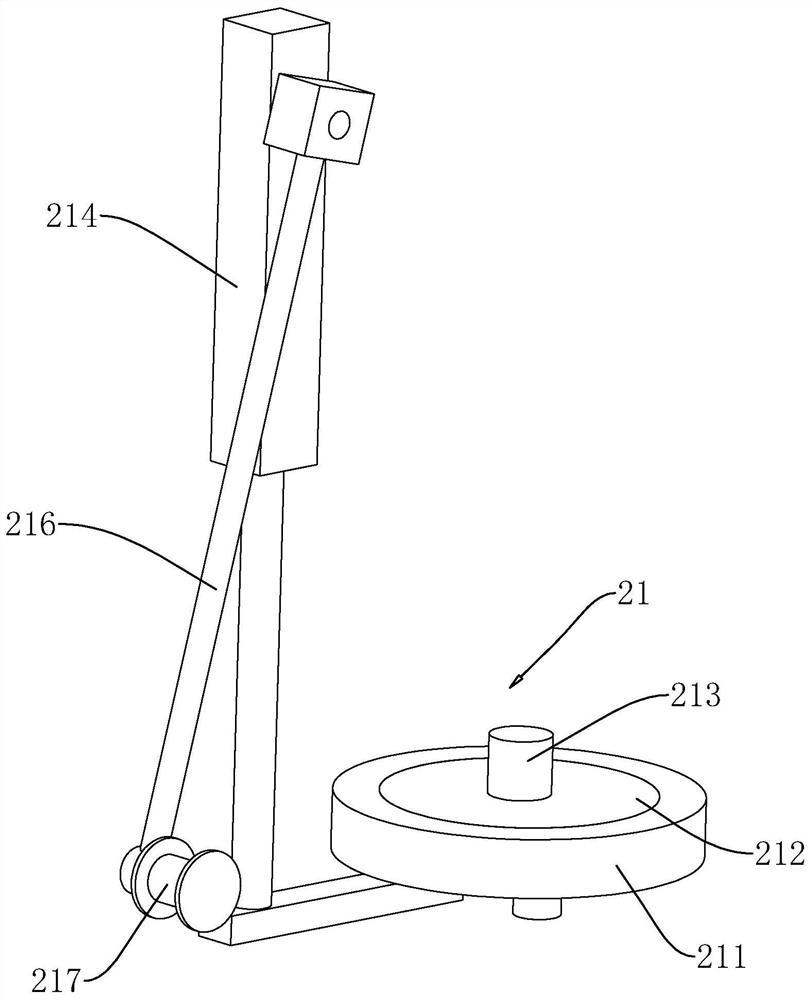
[0036] Such as figure 2 , image 3As shown, the support base 21 includes a coaxial fixed disk 211 and a rotating disk 212 , the rotating disk 212 is located inside the fixed disk 211 , and the rotating disk 212 is rotatably mounted on the center of the fixed disk 211 . The feeding seat 22 is placed vertically and the bottom of the feeding seat 22 is fixedly installed on the fixed disk 211. Between the bottom of the feeding seat 22 a...


PUM


Abstract

The present application relates to a connector terminal punching machine, which includes a punching body, and a feeding device is arranged on one side of the punching body; the feeding device includes a supporting seat, and a feeding seat arranged on the supporting seat A storage bin with a lower end opening facing the support seat is formed in the feeding seat, and a transmission mechanism is arranged around the feeding seat in a circumferential direction, and the transmission mechanism rotates circumferentially along the height direction of the feeding seat; The transmission mechanism is provided with material placement plates, and the material placement plates are distributed at intervals along the rotation direction of the transmission mechanism; the material placement plates facing the central axis of the feeding seat are located in the storage bin, and the adjacent material placement plates are in the At the same height and keep moving synchronously; this application has the effect of improving feeding efficiency and liberating manpower.

Description

technical field [0001] The present application relates to the field of punching machines, in particular to a connector terminal punching machine. Background technique [0002] At present, the terminal block of the connector is an accessory product used to realize electrical connection. With the increasing degree of industrial automation and stricter and more precise industrial control requirements, the amount of terminal blocks is gradually increasing. [0003] In the industrial mass production of connector terminals, the raw material of connector terminals is usually a copper strip wound into a disc shape. During processing, it is necessary to manually place the copper strip on the feeding device, and then place the copper strip One end is fed from the feed port of the punch equipment, and the copper strip is punched by the punch equipment to form connector terminals; finally, the connector terminals are cut and separated, so that independent connector terminals can be obta...

Claims


Application Information

Patent Timeline
Patent Type & Authority Patents(China)
IPC IPC(8): H01R43/16
CPCH01R43/16
Inventor 周如勇彭成宝李子涵梅雯雯赵顺飞
Owner 乐清市嘉得电子有限公司
Why Eureka
Try Eureka