
Polishing equipment for edge opening of high-frequency plate after drilling

A high-frequency board and equipment technology, which is applied in the field of high-frequency board drilling and edge grinding equipment, can solve the problems of high-frequency board damage, time-consuming, laborious, and omission, and achieve the effects of reducing operations, good results, and improving work efficiency

Inactive Publication Date: 2021-02-23
赖学良
View PDF0 Cites 7 Cited by
  • Summary
  • Abstract
  • Description
  • Claims
  • Application Information

AI Technical Summary

Problems solved by technology

[0005] In order to overcome the disadvantages of damage and omission of some high-frequency boards that may be caused by manual grinding, as well as time-consuming and labor-intensive disadvantages, the purpose of the present invention is to provide a high-frequency board drill that can automatically perform grinding, automatically reclaim materials, and is easy to operate. Hole edge grinding equipment

Method used


Image

  • Polishing equipment for edge opening of high-frequency plate after drilling
  • Polishing equipment for edge opening of high-frequency plate after drilling
  • Polishing equipment for edge opening of high-frequency plate after drilling

Examples


Embodiment 1

[0027] A kind of high-frequency plate drilling back edge grinding equipment, such as figure 1 , figure 2 and image 3 As shown, it includes a base 1, a motor 2, a feeding mechanism 3, a clamping mechanism 4 and a grinding mechanism 5, a motor 2 is provided in the middle of the base 1, a feeding mechanism 3 is provided on the front and rear sides of the upper part of the base 1, and a feeding mechanism 3 is provided on the feeding mechanism 3. The clamping mechanism 4 is provided with a grinding mechanism 5 on the middle side of the upper part of the base 1 .

[0028] The feeding mechanism 3 includes a first transmission assembly 31, a first rotating shaft 32, a driving wheel 33, a conveyor belt 34, and a first wedge-shaped rod 35. The front and rear sides of the middle part of the base 1 are rotatably provided with a first rotating shaft 32, and the front first rotating shaft 32 The left side is connected with the output shaft of the motor 2 with a first transmission assemb...

Embodiment 2

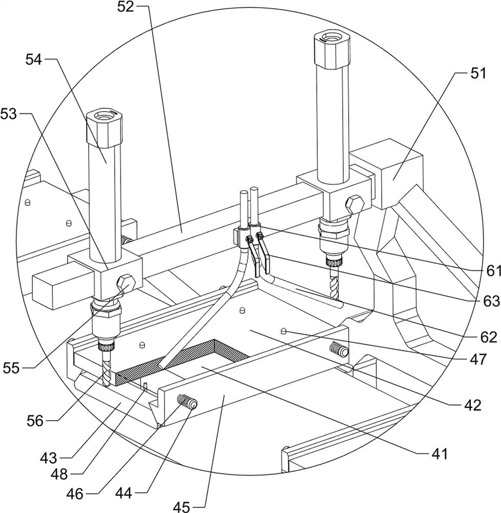
[0033] On the basis of Example 1, such as image 3 , Figure 4 , Figure 5 and Figure 6 As shown, a dust removal mechanism 6 is also included. The dust removal mechanism 6 includes a valve 61, an air duct 62 and an adjustment handle 63. Two valves 61 are arranged in the middle of the second guide rod 52, and an air duct 62 is provided on the lower side of the valve 61. , The middle part of the valve 61 is provided with an adjustment handle 63 which is rotatable.

[0034] When the grinding work is carried out, people open the valve 61, and the direction of the air duct 62 can be controlled by manually rotating the adjustment handle 63, and the air duct 62 will blow out the waste scraps from the grinding, so that the grinding effect is better.

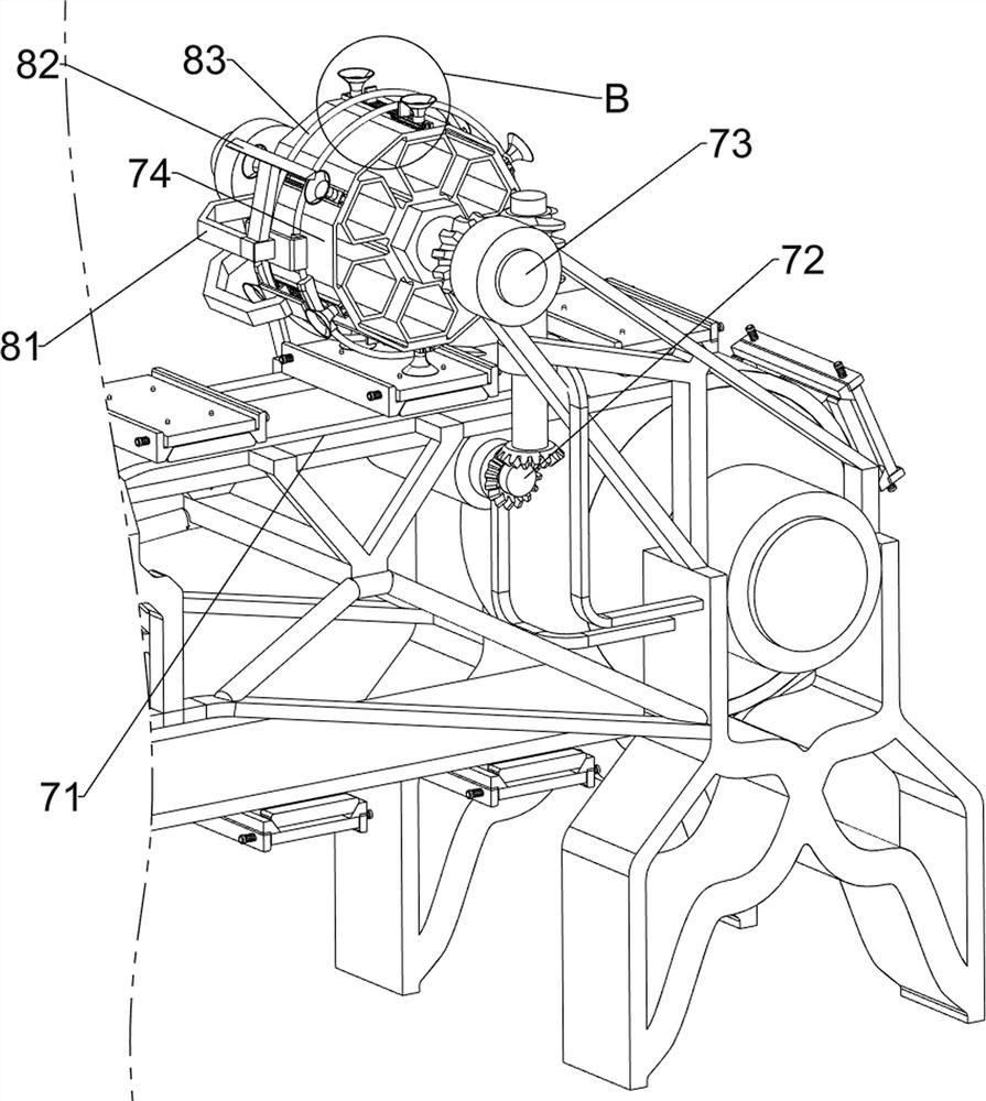
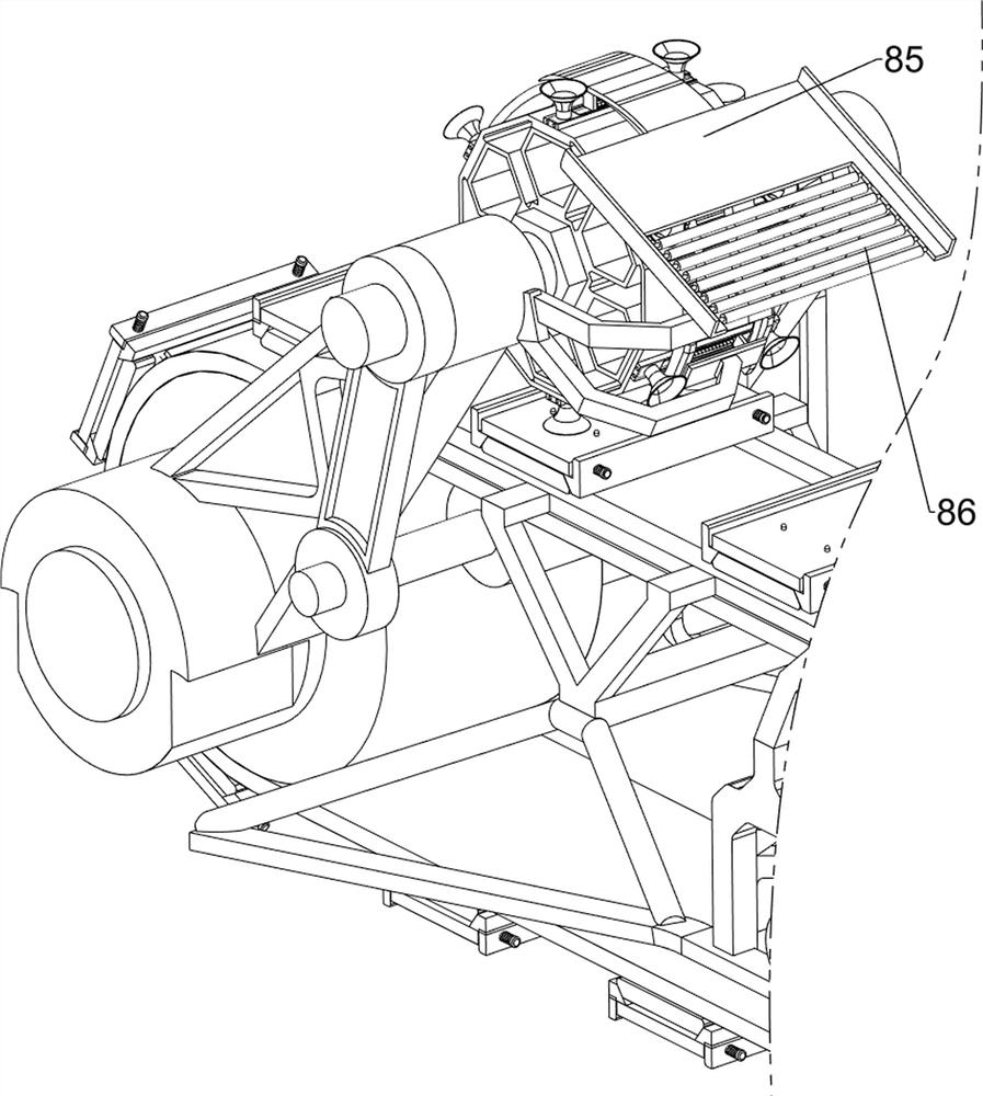
[0035] Also includes a material retrieving mechanism 7, the retrieving mechanism 7 includes a second wedge-shaped rod 71, a second transmission assembly 72, a second rotating shaft 73, a runner 74, a first block 75, a third guide rod...


PUM


Abstract

The invention relates to polishing equipment, in particular to polishing equipment for an edge opening of a high-frequency plate after drilling. The invention aims to provide the polishing equipment for the edge opening of the high-frequency plate after drilling, wherein the equipment is capable of performing automatic polishing and automatically taking materials and is simple to operate. According to the technical scheme, the polishing equipment for the edge opening of the high-frequency plate after drilling comprises a base, a motor, feeding mechanisms, clamping mechanisms, and a polishing mechanism. The motor is arranged in the middle of the base; the feeding mechanisms are arranged at two sides of the upper part of the base; the clamping mechanisms are arranged on the feeding mechanisms; and the polishing mechanism is arranged at the middle side of the upper portion of the base. The equipment has the beneficial effects that under the action of the polishing mechanism, people startan air grinder and the motor, the motor can drive a first transmission assembly to rotate, clamping assemblies can drive wedge-shaped baffles to move towards the inner side, and therefore the high-frequency plate is clamped, and a bottom plate can continue to drive the high-frequency plate to move towards the rear side; and when the high-frequency plate is in contact with a cutter, the cutter canpolish the high-frequency plate, so that the working efficiency of people is effectively improved.

Description

technical field [0001] The invention relates to a grinding device, in particular to a grinding device for the edge after drilling a high-frequency plate. Background technique [0002] High-frequency board is a special circuit board with high electromagnetic frequency. Its physical properties, precision and technical parameters are very high. It is often used in automotive anti-collision systems, satellite systems, radio systems and other fields. [0003] After people drill the high-frequency board, burrs and other waste materials may appear on the edge, so generally people will polish it. When grinding the edge, the high-frequency board is usually manually held and moved to the grinding mechanism. Grinding, when people manually grind, it may cause damage and omission of some high-frequency boards, and it will cause time-consuming and labor-intensive situations. The grinding device may also cause the operator to contact with it and cause injury, so as to reduce work efficienc...

Claims


Application Information

Patent Timeline
Patent Type & Authority Applications(China)
IPC IPC(8): B24B9/00B24B41/06B24B55/06B24B41/00B24B47/04
CPCB24B9/00B24B41/005B24B41/068B24B47/04B24B55/06
Inventor 赖学良赖致升
Owner 赖学良
Learn More