Catalytic ozonation treatment device for sewage

A technology of ozone catalytic oxidation and treatment device, applied in water/sewage treatment, oxidized water/sewage treatment, water/sludge/sewage treatment, etc., can solve the problems of inconvenient replacement of the device, low dissolution rate, low efficiency, etc.

Active Publication Date: 2021-02-23
SHANDONG LONGANTAI ENVIRONMENTAL PROTECTION SCI TECH CO LTD
View PDF9 Cites 8 Cited by
  • Summary
  • Abstract
  • Description
  • Claims
  • Application Information

AI Technical Summary

Problems solved by technology

[0002] Ozone can not only kill algae in water, but also act as scale and corrosion inhibitors without secondary pollution. It is a strong oxidant that can convert toxic pollutants into non-toxic substances. It has strong oxidation ability in treating wastewater and can decompose general Oxidants are difficult to destroy organic matter, and the reaction is safe and the time is short, so it is widely used in sewage treatment. However, in the existing sewage treatment process, because the ozone bubbles will continue to float in the sewage, the utilization rate of ozone is low. The dissolution rate in water is low, and the sewage treatment effect requires a long time of ozone, so that the discharged gas still contains a large amount of unused ozone, which makes the process cost high and the efficiency is too low, and it will be used for a period of time Afterwards, the activity of the ozone catalyst decreases, and the catalyst needs to be replaced, but the existing device is inconvenient to replace

Method used


Image

  • Catalytic ozonation treatment device for sewage
  • Catalytic ozonation treatment device for sewage
  • Catalytic ozonation treatment device for sewage

Examples


Embodiment Construction

[0015] In order to make the purpose, technical solutions and advantages of the embodiments of the present invention clearer, the technical solutions in the embodiments of the present invention will be clearly and completely described below in conjunction with the drawings in the embodiments of the present invention. Obviously, the described embodiments It is a part of embodiments of the present invention, but not all embodiments. Based on the embodiments of the present invention, all other embodiments obtained by persons of ordinary skill in the art without creative efforts fall within the protection scope of the present invention.

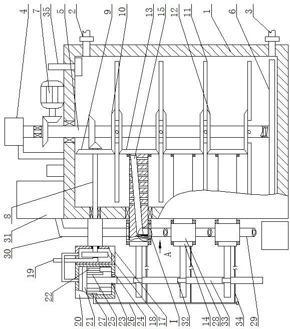
[0016]A sewage ozone catalytic oxidation treatment device, as shown in the figure, includes a tank body 1, the upper part of one side of the tank body 1 is fixedly connected to one end of the liquid inlet pipeline 2 with a shut-off valve, and the bottom of one side of the tank body 1 is fixedly connected with a belt One end of the outlet pipe 3 wi...


PUM


Abstract

A catalytic ozonation treatment device for sewage comprises a tank body, the upper portion of one side of the tank body is fixedly connected with one end of a liquid inlet pipeline with a stop valve,the bottom of one side of the tank body is fixedly connected with one end of a liquid outlet pipeline with a stop valve, and an ozone generator is fixedly installed on the top face of the outer wall of the tank body. The gas outlet end of the ozone generator is connected with the upper end of a gas inlet pipeline through a sealing bearing, the gas inlet pipeline penetrates through the top surfaceof the tank body and is rotationally connected with the top surface of the tank body, a one-way valve is fixedly mounted on the lower side in the gas inlet pipeline, and a transverse pipe is fixedly mounted at the lower end of the gas inlet pipeline and communicates with the interior of the gas inlet pipeline;A plurality of evenly-distributed air holes are formed in the bottom face of the periphery of the transverse pipe. A driving device capable of driving the gas inlet pipeline to rotate is fixedly mounted on the top surface of the outer wall of the tank body. According to the device, reverse rotation of two adjacent layers of stirring rods can be realized, so that bubbles can be crushed, ozone and sewage are fully reacted, the sewage treatment effect is improved, the ozone content in tail gas is reduced, and the resource utilization rate is increased.

Description

technical field [0001] The invention belongs to the field of sewage treatment, in particular to a sewage ozone catalytic oxidation treatment device. Background technique [0002] Ozone can not only kill algae in water, but also act as scale and corrosion inhibitors without secondary pollution. It is a strong oxidant that can convert toxic pollutants into non-toxic substances. It has strong oxidation ability in treating wastewater and can decompose general Oxidants are difficult to destroy organic matter, and the reaction is safe and the time is short, so it is widely used in sewage treatment. However, in the existing sewage treatment process, because the ozone bubbles will continue to float in the sewage, the utilization rate of ozone is low. The dissolution rate in water is low, and the sewage treatment effect requires a long time of ozone, so that the discharged gas still contains a large amount of unused ozone, which makes the process cost high and the efficiency is too l...

Claims


Application Information

Patent Timeline
Patent Type & Authority Applications(China)
IPC IPC(8): C02F1/78
CPCC02F1/725C02F1/78
Inventor 代春龙魏明勇张华东孙垂刚高庆刚
Owner SHANDONG LONGANTAI ENVIRONMENTAL PROTECTION SCI TECH CO LTD
Why Eureka
Try Eureka