Cold-start preheating system of engine

A cold start and engine technology, applied in the direction of engine start, engine components, machines/engines, etc., can solve the problems of high energy consumption for preheating, complicated structure and control, and diesel condensation, so as to reduce the cost of preheating and improve The effect of the warm-up effect

Inactive Publication Date: 2021-02-23
湖北美标康盛动力科技有限公司
View PDF0 Cites 0 Cited by
  • Summary
  • Abstract
  • Description
  • Claims
  • Application Information

AI Technical Summary

Problems solved by technology

[0002] Although the diesel engine has the advantages of good thermal efficiency and economy, but because the fuel it uses is diesel, which is more viscous than gasoline, it will condense, wax, and block the oil pipe in high-altitude and other low-temperature environments. and other problems, making the diesel engine unable to start
[0003] In the prior art, when the diesel generator is cold started, the following preheating methods are mainly adopted: a separately configured fuel oil water jacket heater (such as a liquid fuel oil heater) is used to burn diesel oil to heat the coolant in the water jacket, and through the coolant The circulating flow in the diesel engine is used to preheat the diesel engine. The structure of the liquid fuel heater is divided into a combustion head, a combustion chamber, a water jacket and a water pump. In addition, it is necessary to configure corresponding control circuits and programs for fuel supply and ignition. The structure and The control is complex and the cost is high, and there is also the disadvantage of high energy consumption and high cost for preheating

Method used


Image

  • Cold-start preheating system of engine
  • Cold-start preheating system of engine
  • Cold-start preheating system of engine

Examples


Embodiment Construction

[0025] It should be noted that, in the case of no conflict, the embodiments of the present invention and the features in the embodiments can be combined with each other.

[0026] In describing the present invention, it should be understood that the terms "center", "longitudinal", "transverse", "upper", "lower", "front", "rear", "left", "right", " The orientations or positional relationships indicated by "vertical", "horizontal", "top", "bottom", "inner" and "outer" are based on the orientations or positional relationships shown in the drawings, and are only for the convenience of describing the present invention and Simplified descriptions, rather than indicating or implying that the device or element referred to must have a particular orientation, be constructed and operate in a particular orientation, and thus should not be construed as limiting the invention. In addition, the terms "first", "second", etc. are used for descriptive purposes only, and should not be understood ...


PUM


Abstract

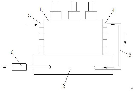
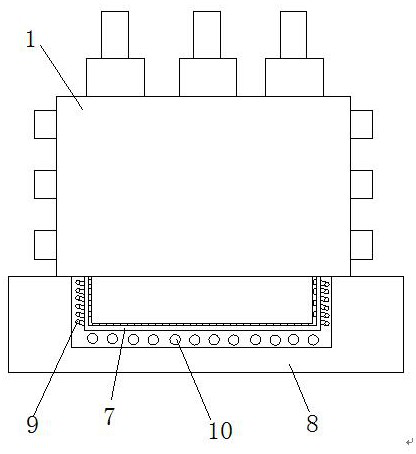
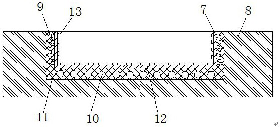
The invention discloses a cold-start preheating system of an engine. An engine shell is installed on a heating groove, the heating groove comprises an outer groove body and an inner groove body, the inner groove body is installed in the outer groove body, heating wires are arranged between the periphery of the inner groove body and the outer groove body, the heating wires are electrically connected to a vehicle-mounted controller, and a circulating heating air pipe is arranged between the lower bottom of the inner groove body and the outer groove body; and an air inlet channel and an air outlet channel are formed in the upper part of the engine shell separately, the air outlet channel communicates with one end of the circulating heating air pipe through a connecting pipe, and the other endof the circulating heating air pipe communicates with a smoke exhaust pipe. The cold-start preheating system of the engine has the following beneficial effects: the vehicle-mounted controller, the heating groove and the engine shell are arranged, the engine shell is directly placed on the heating groove to be heated, a complex structure and a circuit system do not need to be additionally arranged, the heating groove carries out preheating in a mode of electric heating and auxiliary heating of engine hot air, the preheating effect is improved, and meanwhile heat is fully utilized, so that thepreheating effect is greatly improved, and meanwhile the preheating cost is reduced.

Description

technical field [0001] The invention relates to the technical field of sleeper handling, in particular to an engine cold start preheating system. Background technique [0002] Although the diesel engine has the advantages of good thermal efficiency and economy, but because the fuel it uses is diesel, which is more viscous than gasoline, it will condense, wax, and block the oil pipe in high-altitude and other low-temperature environments. And other problems, so that the diesel engine can not start. [0003] In the prior art, when the diesel generator is cold started, the following preheating methods are mainly adopted: a separately configured fuel oil water jacket heater (such as a liquid fuel oil heater) is used to burn diesel oil to heat the coolant in the water jacket, and through the coolant The circulating flow in the diesel engine is used to preheat the diesel engine. The structure of the liquid fuel heater is divided into a combustion head, a combustion chamber, a wat...

Claims


Application Information

Patent Timeline
IPC IPC(8): F02N19/10
CPCF02N19/10
Inventor 张辉
Owner 湖北美标康盛动力科技有限公司
Why Eureka
Try Eureka