Smoke treatment device, smoke treatment system and smoke treatment method

A technology for flue gas treatment and flue gas, which is applied in waste heat treatment, climate sustainability, and greenhouse gas reduction, and can solve problems such as white smoke from chimneys

Pending Publication Date: 2021-02-23
LUOYANG RUICHANG PETROCHEM EQUIP
View PDF1 Cites 0 Cited by
  • Summary
  • Abstract
  • Description
  • Claims
  • Application Information

AI Technical Summary

Problems solved by technology

[0004] In view of this, the present invention aims to propose a flue gas treatment device, a flue gas treatment system, and a flue gas treatment method to solve the problem of white smoke from chimneys in the flue gas discharge process in the prior art

Method used


Image

  • Smoke treatment device, smoke treatment system and smoke treatment method
  • Smoke treatment device, smoke treatment system and smoke treatment method
  • Smoke treatment device, smoke treatment system and smoke treatment method

Examples


Embodiment 1

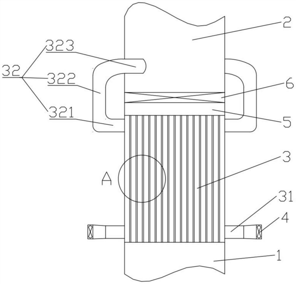
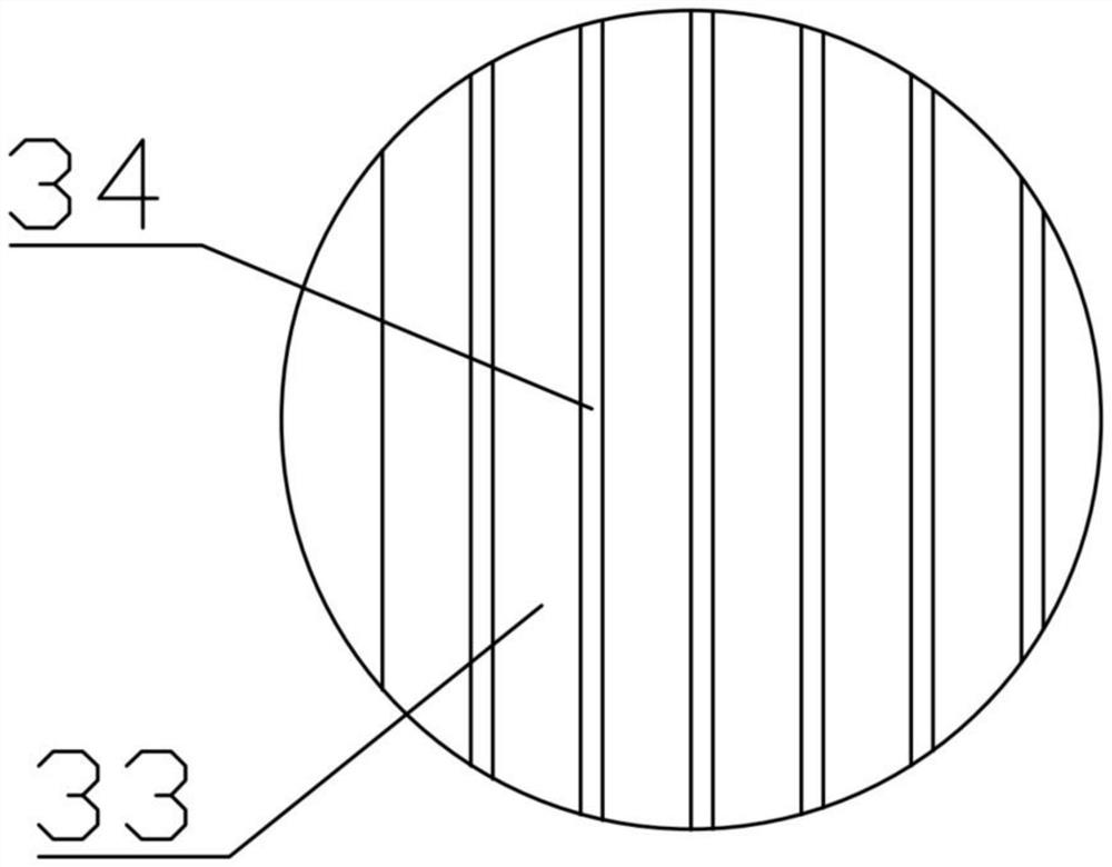
[0041] In order to solve the problem that the existing flue gas treatment system tends to emit white smoke in the process of flue gas discharge after the flue gas is treated, as attached Figure 1-2 As shown, this embodiment proposes a flue gas treatment device. The flue gas treatment device includes a flue gas inlet pipe 1, a flue gas outlet pipe 2, and a heat exchange device 3. The flue gas inlet pipe 1 and the heat exchange device 3 The inlet of the flue gas passage 34 is connected, and the flue gas outlet pipe 2 is connected with the outlet of the flue gas passage 34 of the heat exchange device 3. The heat exchange device 3 is provided with an air inlet pipe 31 and an air outlet pipe 32. The air outlet The inlet end of the pipe 32 communicates with the outlet of the air channel 33 of the heat exchange device 3 , and the outlet end of the air outlet pipe 32 communicates with the flue gas outlet pipe 2 , so that the air after heat exchange and the flue gas are mixed in the ai...

Embodiment 2

[0050] Considering that in the flue gas channel 34, the flue gas often has a relatively high flow rate, after heat exchange, it will still carry a part of the condensed water droplets to move upwards and enter the flue gas outlet pipe 2, and this part of the condensed water droplets will be It affects the humidity of the mixed flue gas, which is not conducive to ensuring the elimination of white smoke from the chimney.

[0051] Therefore, in order to solve this problem, the attached Figure 1-3 As shown, this embodiment further improves the flue gas treatment device on the basis of embodiment 1, specifically:

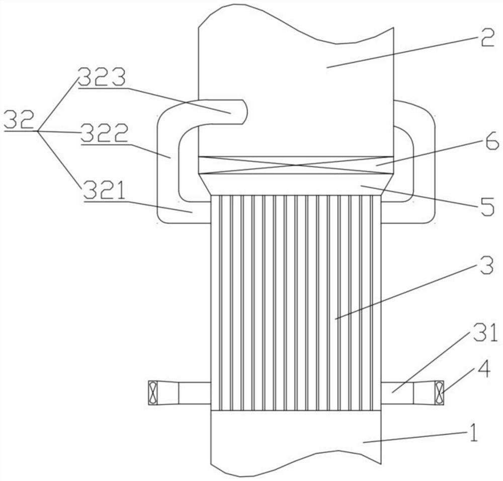
[0052] A deceleration pipe 5 is arranged between the flue gas outlet pipe 2 and the heat exchange device 3 , the inlet end of the deceleration pipe 5 communicates with the flue gas passage 34 of the heat exchange device 3 , and the outlet end of the deceleration pipe 5 It communicates with the flue gas outlet pipe 2; wherein, the cross-sectional area of ​​the decelerat...

Embodiment 3

[0058] In the flue gas outlet pipe 2, in order to ensure that the low temperature flue gas is fully mixed with the hot dry air, as attached Figure 1-4 As shown, this embodiment further improves the flue gas treatment device on the basis of embodiment 1 or embodiment 2, specifically:

[0059] The inlet end of the flue gas outlet pipe 2 communicates with the outlet of the flue gas channel 34 of the heat exchange device 3, and the outlet end of the flue gas outlet pipe 2 communicates with the chimney or the external atmosphere, thereby ensuring that the flue gas is It can be discharged through the inlet end of the flue gas outlet pipe 2 and the outlet end of the flue gas outlet pipe 2 in sequence.

[0060] At the same time, a mixing space 21 is provided in the flue gas outlet pipe 2 to provide a space for the mixing process of low-temperature flue gas formed after heat exchange and hot dry air.

[0061] The air outlet pipe 32 communicates with the smoke outlet pipe 2, specifica...


PUM


Abstract

The invention provides a smoke treatment device, a smoke treatment system and a smoke treatment method, the smoke treatment device comprises a smoke inlet pipe, a smoke outlet pipe, a heat exchange device, an air inlet pipe and an air outlet pipe, and the smoke inlet pipe is communicated with a smoke channel inlet of the heat exchange device. The smoke outlet pipe is communicated with a smoke channel outlet of the heat exchange device, the inlet end of the air outlet pipe is communicated with an air channel outlet of the heat exchange device, the outlet end of the air outlet pipe is communicated with the smoke outlet pipe, so that heat-exchanged air and smoke are mixed in the air outlet pipe, and in a smoke channel, the flowing direction of the smoke is vertically upward. According to thesmoke treatment device, the smoke treatment system and the smoke treatment method, the smoke treatment device is arranged, so that the situation that white smoke is emitted from a chimney in the smokeemission process in industrial production is avoided.

Description

technical field [0001] The invention relates to the technical field of environmental protection, in particular to a flue gas treatment device, a flue gas treatment system and a flue gas treatment method. Background technique [0002] The problem of ultra-low emission of smoke exhaust from power plant boilers and petrochemical heating furnaces has attracted widespread attention from all walks of life and the country's strong attention. Especially in developed areas such as the Yangtze River Delta, Pearl River Delta and Beijing-Tianjin along the southeast coast, in order to meet the requirements of ultra-low emission standards, wet desulfurization accounts for 93% of the flue gas desulfurization devices currently in operation, and the water in the flue gas after wet desulfurization The steam is in a nearly saturated state. If it is discharged directly through a conventional chimney, the water vapor in the flue gas will quickly turn into a supersaturated state after entering th...

Claims


Application Information

Patent Timeline
IPC IPC(8): F23J15/06F23J15/08F28B1/06F28C3/02F28D9/00F28F9/24F27D17/00
CPCF23J15/06F23J15/08F27D17/00F28B1/06F28C3/02F28D9/0037F28F9/24Y02E20/30
Inventor 邵松吕凤万大阳唐聚园程宁宁岳晓伟
Owner LUOYANG RUICHANG PETROCHEM EQUIP
Why Eureka
Try Eureka