
Method for establishing simulated earth surface depth domain velocity model

A technology of velocity model and establishment method, which is applied in seismology, geophysical measurement, seismic signal processing, etc. It can solve the problems of low signal-to-noise ratio and low velocity model accuracy affecting the final imaging accuracy, and achieve the effect of improving migration accuracy

Pending Publication Date: 2021-02-23
CHINA PETROLEUM & CHEM CORP +1
View PDF10 Cites 0 Cited by
  • Summary
  • Abstract
  • Description
  • Claims
  • Application Information

AI Technical Summary

Problems solved by technology

[0009] The purpose of the present invention is to overcome the problem in the prior art that the low accuracy of the velocity model affects the final imaging accuracy, and to provide a simulation of the establishment of a velocity model in the depth domain of the surface for the undulating surface areas with low signal-to-noise ratio and inaccurate velocity method

Method used


Image

  • Method for establishing simulated earth surface depth domain velocity model
  • Method for establishing simulated earth surface depth domain velocity model
  • Method for establishing simulated earth surface depth domain velocity model

Examples


Embodiment Construction

[0048] The present invention will be further described in detail below in conjunction with test examples and specific embodiments. However, it should not be understood that the scope of the above subject matter of the present invention is limited to the following embodiments, and all technologies realized based on the content of the present invention belong to the scope of the present invention.

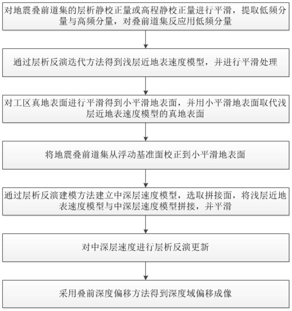
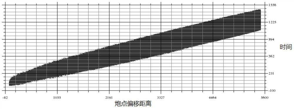
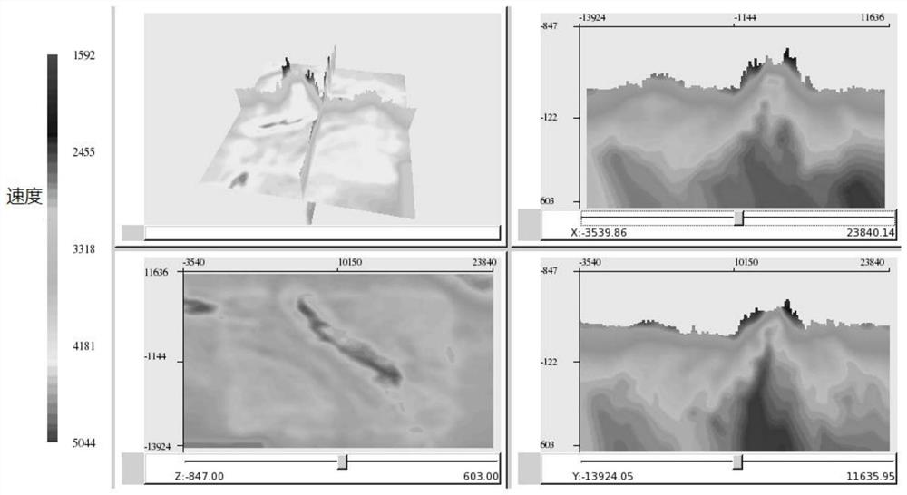
[0049] Existing depth-domain velocity modeling techniques are mainly based on tomographic inversion-driven velocity modeling in the middle and deep layers, and it is difficult to obtain updated shallow-layer velocities with tomographic inversion methods. Therefore, the present invention utilizes the seismic pre-stack gathers in the work area that have been pre-stacked, picks up the first arrival of the single shot in the work area, and the surface elevation of the work area, the floating datum of the work area, the tomographic static correction value of the work area (or elevation sta...


PUM


Abstract

The invention discloses a method for establishing a simulated earth surface depth domain velocity model. The method comprises the following steps: smoothing a tomography static correction value or a high-range static correction value of a seismic pre-stack gather, extracting a low-frequency component and a high-frequency component, and reflecting the low-frequency component for the pre-stack gather; according to the full-offset first arrival of the work area, obtaining a shallow velocity model through a chromatography inversion iteration method, and carrying out smoothing processing on the shallow velocity model; smoothing the real ground surface of the work area to obtain a simulated ground surface, and replacing the real ground surface of the shallow velocity model with the simulated ground surface; correcting the seismic pre-stack gather from the floating reference surface to the simulated ground surface, the correction time being obtained through a two-side depth difference and a replacement speed; and selecting a splicing surface, splicing the shallow velocity model and the middle-deep velocity model, smoothing the splicing surface, obtaining a simulated earth surface depth domain velocity model, carrying out chromatography inversion updating on the middle-deep velocity, and improving the velocity precision is improved.

Description

technical field [0001] The invention relates to the technical field of pre-stack depth migration imaging in the process of oil exploration reflected wave seismic data processing, in particular to a method for establishing a simulated surface depth domain velocity model. Background technique [0002] At present, domestic shale gas exploration and development are in the ascendant, and shale gas resources have great potential. However, the thickness of high-quality shale reservoirs is relatively thin, and the development process relies on horizontal well technology, which requires high depth accuracy. Prestack depth migration technology is an ideal technology to solve the problem of seismic data imaging in areas with complex structures and severe lateral velocity changes. Depth domain imaging results of seismic data can play an important supporting role in high-precision exploration and development of shale gas (fine structure interpretation, precise fault location, oil and ga...

Claims


Application Information

Patent Timeline
Patent Type & Authority Applications(China)
IPC IPC(8): G01V1/30
CPCG01V1/303G01V2210/6222
Inventor 沈杰徐天吉唐建明马昭军王金龙张剑飞林娜喻勤凌航曾涛王斌涂远艮
Owner CHINA PETROLEUM & CHEM CORP
Learn More