
A Multi-View Based Aircraft Skin Defect Detection Method

A technology of aircraft skin and detection method, which is applied in the direction of optical testing flaws/defects, measuring devices, computer components, etc., and can solve problems such as unmentioned image acquisition methods, affecting detection accuracy, and aircraft structural damage. Achieve the effects of enhancing recognition coverage, realizing maintenance management, and high recognition accuracy

Active Publication Date: 2021-03-30
NAT UNIV OF DEFENSE TECH
View PDF1 Cites 0 Cited by
  • Summary
  • Abstract
  • Description
  • Claims
  • Application Information

AI Technical Summary

Problems solved by technology

During the flight of the aircraft, under the action of external force, after the undiscovered small defects expand to critical conditions, the defects will rapidly expand and enlarge, resulting in structural damage to the aircraft, which is very likely to cause the aircraft to disintegrate in the air and cause unpredictable disasters
[0003] Machine vision is to replace the human eye with a machine, convert the captured results into an image signal and send it to the image processing system, and make judgments and measurements. Generally, a single image scanning method or a mobile robot scanning method is used to detect the aircraft skin , the efficiency of this method is low, so how to improve the detection efficiency is the key link of the research
[0004] Patent CN202010058064.2 discloses a method based on the detection and classification of aircraft skin surface defects. It introduces the method of aircraft skin detection and classification, and mainly solves the problem of image processing. It does not mention the method of image acquisition, which will affect The accuracy of its detection

Method used


Image

  • A Multi-View Based Aircraft Skin Defect Detection Method
  • A Multi-View Based Aircraft Skin Defect Detection Method
  • A Multi-View Based Aircraft Skin Defect Detection Method

Examples


Embodiment Construction

[0031] The following will clearly and completely describe the technical solutions in the embodiments of the present invention with reference to the accompanying drawings in the embodiments of the present invention. Obviously, the described embodiments are only some, not all, embodiments of the present invention. Based on the embodiments of the present invention, all other embodiments obtained by persons of ordinary skill in the art without making creative efforts belong to the protection scope of the present invention.

[0032] In the description of the present invention, it should be understood that the orientations or positional relationships indicated by "front", "rear", "left", "right", "upper" and "lower" in terms are based on those shown in the accompanying drawings. Orientation or positional relationship is only for the convenience of describing the present invention and simplifying the description, and does not indicate or imply that the referred device or element must ...


PUM


Abstract

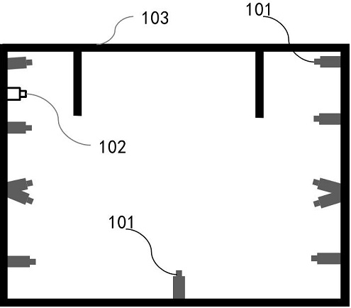
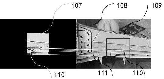
The invention discloses a multi-angle-based aircraft skin defect detection method, which includes a detection system, and the detection system includes a bracket, a fixed camera module and a mobile camera module arranged on the bracket, and a processing device connected to the fixed camera module and the mobile camera module. Module, the fixed camera module adopts multi-channel signal acquisition and integrates the camera into the processing module for rough detection of the skin through the hub management; the mobile camera module is managed separately in a wireless way, and the mobile camera module is controlled and imaged by wireless signals Transmission; its detection method comprises the following steps: first adopt fixed camera module to carry out coarse detection to aircraft skin, obtain the aircraft skin detection probability, the resolution of camera and the selection of focal length are obtained according to target detection probability; then mobile camera module passes in The aircraft skin is moved on the bracket for fine inspection, and finally the image matching algorithm is used for alignment inspection to improve the accuracy of inspection.

Description

technical field [0001] The invention relates to the field of aircraft skin defect detection, in particular to a method for detecting aircraft skin defects based on multi-view angles. Background technique [0002] The aircraft skin is a layer of lead alloy metal on the surface of the aircraft, which constitutes the shape of the aircraft and has the functions of maintaining aerodynamics and transmitting loads. During the whole flight process of the aircraft from take-off to landing, the skin will be subjected to constant and changing pressure from the outside world, and the skin will expand and contract periodically for a long time, and tiny fatigue cracks are easily formed on the surface; my country has a vast territory and natural The environment is complex, and aircrafts in various places have been in different natural environments for a long time, and the skin and rivets are prone to corrosion after contact with corrosive factors. Under the joint action of fatigue damage a...

Claims


Application Information

Patent Timeline
Patent Type & Authority Patents(China)
IPC IPC(8): G06T7/00G06T7/40G06K9/62G06K9/46G01N21/01G01N21/88
CPCG06T7/0002G06T7/40G01N21/01G01N21/8851G01N2021/0112G01N2021/8887G06V10/462G06F18/22
Inventor 曾向荣钟志伟刘衍张政
Owner NAT UNIV OF DEFENSE TECH
Learn More