Cutter temperature detecting and cooling device of automatic machine tool

A cooling device and tool technology, applied in positioning devices, manufacturing tools, measuring/indicating equipment, etc., can solve the problems of tool overheating, tool damage, low sensitivity, etc., and achieve the effect of avoiding falling off

Pending Publication Date: 2021-02-26
安徽锦希自动化科技有限公司
View PDF6 Cites 0 Cited by
  • Summary
  • Abstract
  • Description
  • Claims
  • Application Information

AI Technical Summary

Problems solved by technology

[0003] CNC machine tools tend to overheat the tool when used for a long time, so it is necessary to cool the tool, but the existing cooling device is inconvenient to operate, wastes labor during use, and has low sensitivity. Most of the operators judge the temperature of the tool based on experience Thus cooling it, it is easy to cause damage to the tool, thereby reducing the practicability of the cooling device

Method used


Image

  • Cutter temperature detecting and cooling device of automatic machine tool
  • Cutter temperature detecting and cooling device of automatic machine tool
  • Cutter temperature detecting and cooling device of automatic machine tool

Examples


Embodiment 1

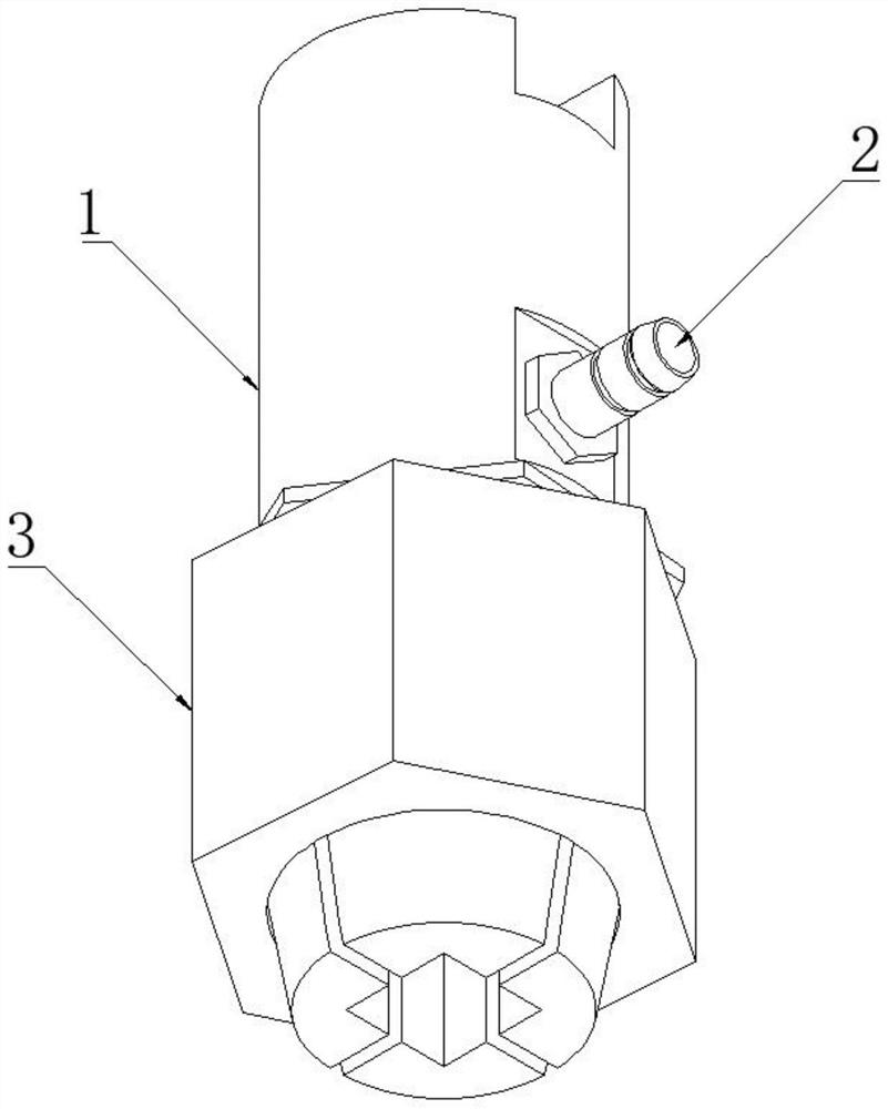
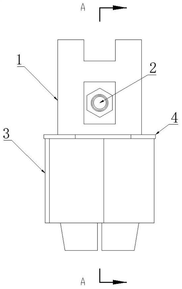
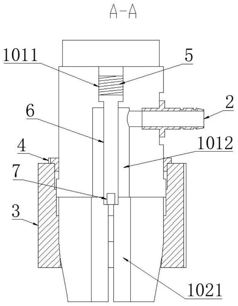
[0032] see Figure 1-5 As shown, the present invention is a tool temperature detection and cooling device for an automatic machine tool, including a fixing part 1, and the fixing part 1 includes a connecting part 101 and a mounting part 102, and a protrusion is provided on the outside of the connection between the connecting part 101 and the mounting part 102 103; the connecting part 101 is provided with diversion grooves 1012 distributed in the axial direction, and the end of the connecting part 101 is provided with deep holes 1011 communicating with the diversion grooves 1012; the installation part 102 is provided with rectangular grooves distributed in the axial direction 1021; the diversion groove 1012 communicates with the rectangular groove 1021; the ejector rod 6 is installed in the deep hole 1011, the end of the ejector rod 6 is fixed with a temperature sensor 7, and the end of the temperature sensor 7 is fixed into the rectangular groove 1021; The end face of the moun...

Embodiment 2

[0039] see Figure 1-4 , 6, the present invention is a tool temperature detection and cooling device for an automatic machine tool, including a fixture 1, and the fixture 1 includes a connecting part 101 and a mounting part 102, and the outside of the connection between the connecting part 101 and the mounting part 102 is provided with Protrusion 103; the connecting part 101 is provided with guide grooves 1012 distributed in the axial direction, and the end of the connecting part 101 is provided with deep holes 1011 communicating with the guide grooves 1012; the installation part 102 is provided with axially distributed Rectangular groove 1021; diversion groove 1012 communicates with rectangular groove 1021; ejector rod 6 is installed in deep hole 1011, the end of ejector rod 6 is fixed with temperature sensor 7, and the end with temperature sensor 7 is fixed into rectangular groove 1021 at the same time Inside; the end surface of the installation part 102 is provided with a n...


PUM


Abstract

The invention discloses a cutter temperature detecting and cooling device of an automatic machine tool, and relates to the technical field of machine tool cooling devices. The cutter temperature detecting and cooling device comprises a fixing piece; the fixing piece comprises a connecting part and an installing part; a protrusion is arranged on the outer side of the connecting position of the connecting part and the installing part; a flow guide groove distributed in the axial direction is formed in the connecting part; a deep hole communicating with the flow guide groove is formed in the endof the connecting part; a rectangular groove distributed in the axial direction is formed in the mounting part; an ejector rod is installed in the deep hole; a temperature sensor is fixed to the end of the ejector rod; a fixing sleeve sleeves the outer side of the mounting part; a limiting piece is cooperatively installed in a gap between the upper end opening of the fixing sleeve and the outer side surface of the mounting part; and the lower end opening of the inner side surface of the fixing sleeve is an inclined surface. The fixing part is composed of the connecting part and the mounting part, a cavity is formed in the formed fixing part, and a connecting pipe communicating with the cavity is installed on the peripheral side surface of the fixing part, so that a cooling liquid conveniently flows to the outer surface of a cutter through the cavity, and heat dissipation of the cutter is conveniently completed.

Description

technical field [0001] The invention belongs to the technical field of bed cooling devices, in particular to a tool temperature detection and cooling device for an automatic machine tool. Background technique [0002] An automatic machine tool with a control system that can logically process programs with control codes or other symbolic instructions, decode them, express them in coded numbers, input them into the numerical control device through the information carrier, and process them by the numerical control device Send out various control signals to control the movement of the machine tool, and automatically process the parts according to the shape and size required by the drawings. [0003] CNC machine tools tend to overheat the tool when used for a long time, so it is necessary to cool the tool, but the existing cooling device is inconvenient to operate, wastes labor during use, and has low sensitivity. Most of the operators judge the temperature of the tool based on e...

Claims


Application Information

Patent Timeline
IPC IPC(8): B23Q3/00B23Q11/10B23Q17/00
CPCB23Q3/00B23Q11/10B23Q17/00
Inventor 李庭庭
Owner 安徽锦希自动化科技有限公司
Why Eureka
Try Eureka