Supercharge Your Innovation With Domain-Expert AI Agents!

Automatic feeding and discharging system for machining

A technology of automatic loading and unloading and material grasping, which is applied in metal processing, conveyor objects, transportation and packaging, etc., can solve the problems of delaying the processing cycle and being unfavorable for the parallel processing of the production line, so as to shorten the processing cycle, improve the processing efficiency, The effect of improving work efficiency

Inactive Publication Date: 2021-02-26
NINGBO XIATUO MACHINERY EQUIP
View PDF6 Cites 2 Cited by
  • Summary
  • Abstract
  • Description
  • Claims
  • Application Information

AI Technical Summary

Problems solved by technology

This single-thread loading and unloading mechanism not only delays the processing cycle, but also is not conducive to the parallel processing of the production line.

Method used


Image

  • Automatic feeding and discharging system for machining
  • Automatic feeding and discharging system for machining
  • Automatic feeding and discharging system for machining

Examples


Embodiment Construction

[0024] The present invention will be further described in detail below in conjunction with the accompanying drawings and specific embodiments.

[0025] In the following embodiments, the same or similar symbols throughout represent the same or similar components or components with the same or similar functions, and the following embodiments described with reference to the accompanying drawings are exemplary and are only used to explain the present invention, rather than understanding To limit the present invention.

[0026] In the description of the present invention, it should be understood that the terms: center, longitudinal, transverse, length, width, thickness, up, down, front, back, left, right, vertical, horizontal, top, bottom, inside, outside, Clockwise, counterclockwise, etc. indicate the orientation or positional relationship based on the orientation or positional relationship shown in the drawings, and are only for the convenience of describing the present invention...


PUM


Abstract

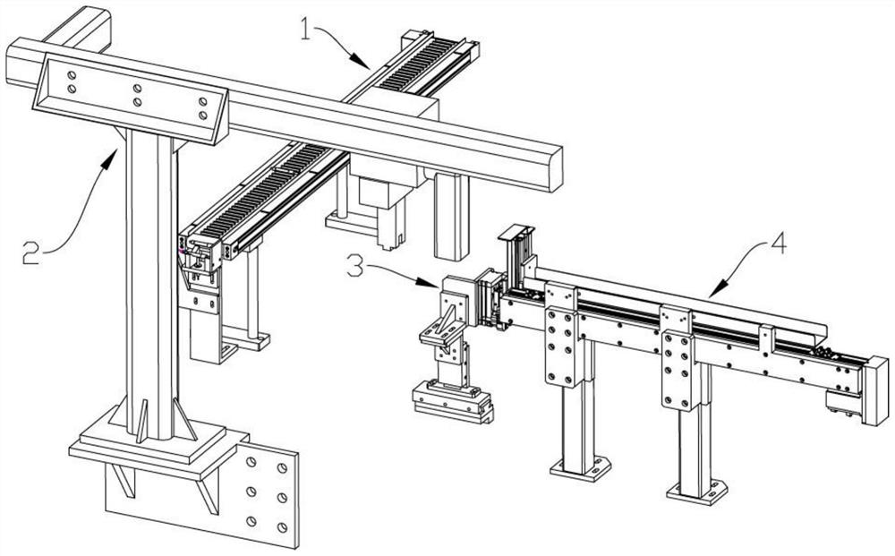
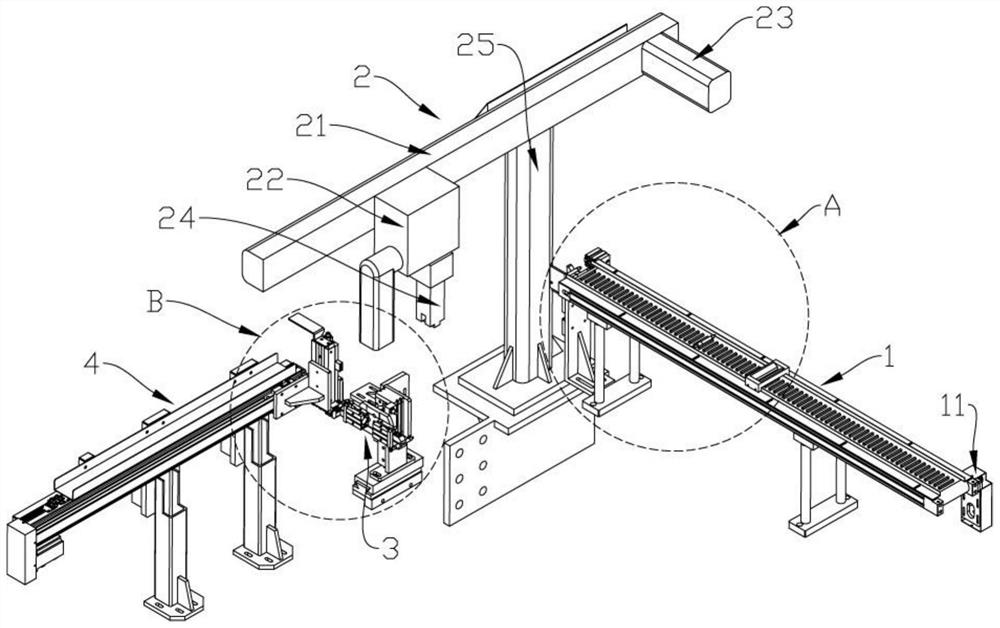
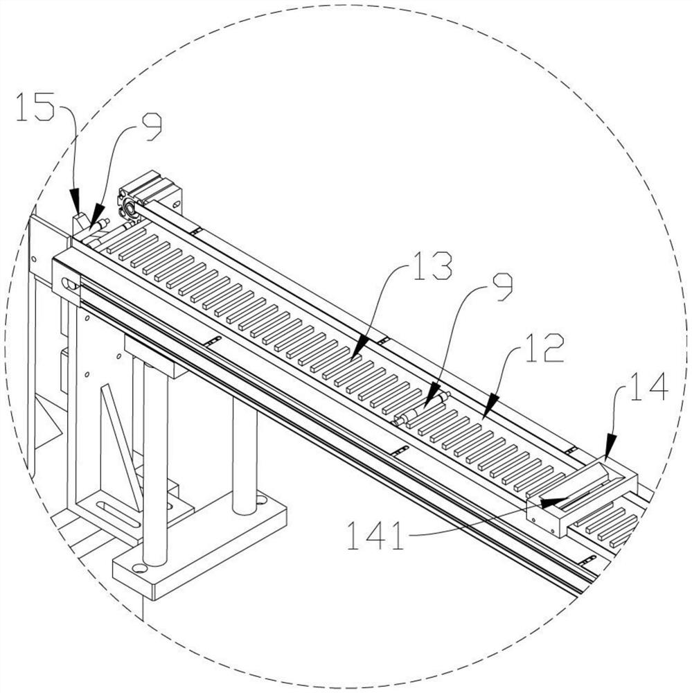
The invention relates to an automatic feeding and discharging system for machining. The automatic feeding and discharging system comprises a conveying mechanism, a feeding mechanism, a turnover mechanism and a discharging mechanism. The conveying mechanism comprises a conveying belt and a conveying belt driving motor. The conveying belt is used for conveying parts one by one. The feeding mechanismcomprises a feeding frame. A movable feeding grabbing assembly is arranged on the feeding frame. A feeding mechanical arm is arranged on the feeding grabbing assembly. The feeding grabbing assembly is used for grabbing the parts on the conveying mechanism and moving the parts to place the parts on the turnover mechanism. The turnover mechanism comprises a rotatable rotating disc. Two symmetricalclamping jaw assemblies are arranged on the rotating disc. Each clamping jaw assembly is provided with a clamping jaw used for clamping the corresponding part. The automatic feeding and discharging system for machining is provided with a feeding truss and a discharging truss which are independent, feeding operation and discharging operation can be conducted at the same time, and by arranging the turnover mechanism, the machining time is shortened, and the machining efficiency is improved.

Description

technical field [0001] The invention belongs to the technical field of material conveying in machining operations, and in particular relates to an automatic loading and unloading system used in machining. Background technique [0002] Shaft parts are one of the typical parts often encountered in hardware accessories. They are mainly used to support transmission parts, transmit torque, bear loads, etc. According to the different structural forms of shaft parts, they can generally be divided into optical shafts, stepped shafts and There are three types of special-shaped shafts; or divided into solid shafts and hollow shafts; or divided into long shafts and short shafts. [0003] When machining shaft parts, machining equipment, such as machine tools, is needed. The parts are fixed on the machining equipment and rotate at a constant speed, and the cutter head processes the parts. In the process of programmed parts machining, it is necessary to use an automatic loading and unloa...

Claims


Application Information

Patent Timeline
Patent Type & Authority Applications(China)
IPC IPC(8): B65G47/04B65G47/90B65G47/248B65G47/34B23Q7/00B23Q7/03B23Q7/04
CPCB65G47/04B65G47/90B65G47/248B65G47/34B23Q7/00B23Q7/03B23Q7/04B23Q7/043
Inventor 谢桂平张瑞平方国锋张波杰陈彬梅舟艇
Owner NINGBO XIATUO MACHINERY EQUIP
Features
  • R&D
  • Intellectual Property
  • Life Sciences
  • Materials
  • Tech Scout
  • Unparalleled Data Quality
  • Higher Quality Content
  • 60% Fewer Hallucinations
Learn More