
Unit mutual standby ozone generation device

An ozone generating device and ozone generator technology, applied in the direction of ozone preparation by discharge method, ozone preparation, oxygen/ozone/oxide/hydroxide, etc., can solve the problem of long time consumption and manpower, and low utilization rate of standby machines , uneconomical operation and other issues, to achieve the effect of narrowing the scope of investigation, shortening maintenance time, and reducing capital occupation

Pending Publication Date: 2021-02-26
山东和创智云环保装备有限公司 +1
View PDF0 Cites 0 Cited by
  • Summary
  • Abstract
  • Description
  • Claims
  • Application Information

AI Technical Summary

Problems solved by technology

If one of the high-voltage electrodes with different numbers fails or one ozone power supply fails, the whole ozone generator needs to be shut down for maintenance and the standby machine should be switched to run at the same time. The frequency of use of the standby machine is only used when the running machine fails. Therefore, the utilization rate of the backup machine is not high, but it takes up a lot of funds
[0004] When a large ozone generator fails, it takes a long time to check and find the faulty electrode among a large number of high-voltage electrodes, and then perform maintenance. This troubleshooting process will consume a long time and manpower
[0005] In addition, because the load on the pollutant treatment site will fluctuate greatly with the seasons, the output adjustment of the large-scale ozone generator in the prior art is generally 30-100%, and the ozone output is configured according to the maximum load of the pollutant treatment, and the ozone is used in the low-load season The output will even be lower than the minimum output of large-scale ozone generators, and there will be a situation of large horses and small carts, which will lead to energy waste due to uneconomical operation

Method used


Image

  • Unit mutual standby ozone generation device
  • Unit mutual standby ozone generation device
  • Unit mutual standby ozone generation device

Examples


Embodiment

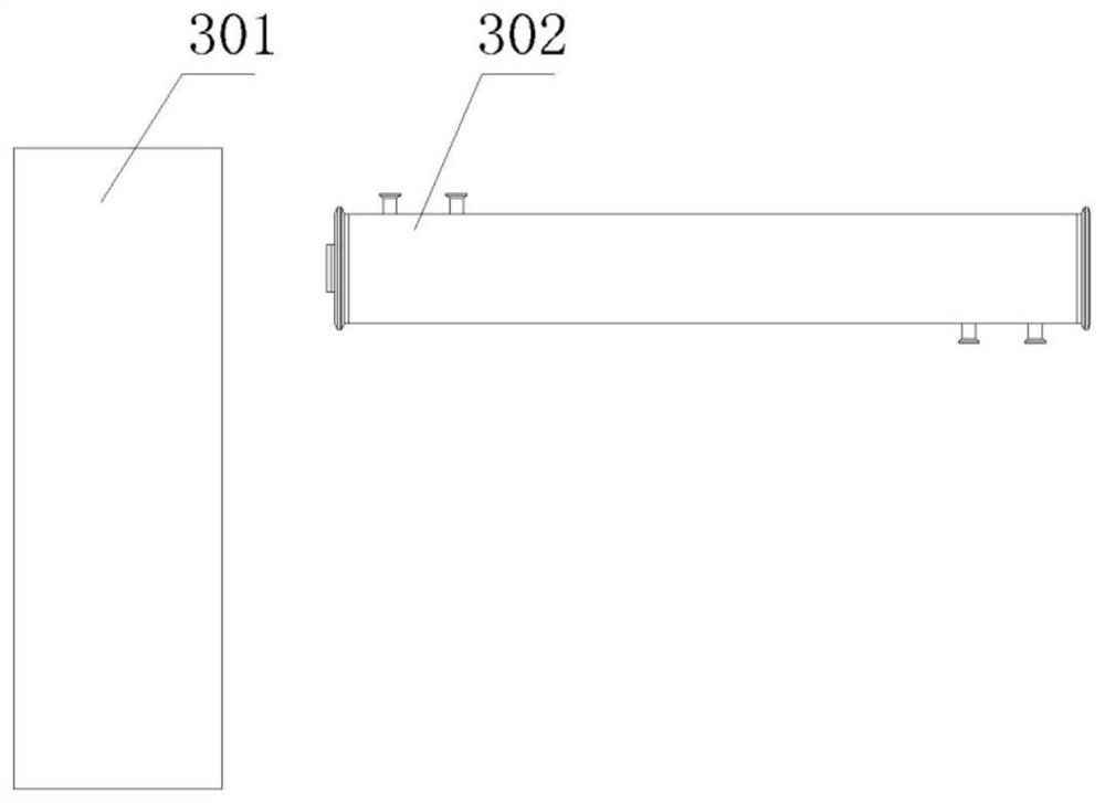
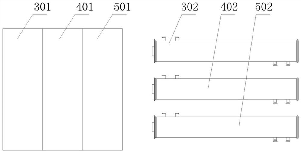
[0025] Example: as attached figure 2 to attach Figure 5 As shown, an ozone generator 600 for unit mutual use includes a skid-mounted base 601, and a first unit ozone generator, a second unit ozone generator, and a third unit ozone generator are installed on the skid-mounted base 601, and the first unit Ozone generator comprises the first unit ozone power supply 301 and the first unit ozone generating chamber 302, the first unit ozone power supply 301 is electrically connected with the first unit ozone generating chamber 302, the second unit ozone generator, the third unit ozone generator and The structure of the first unit ozone generator is the same.

[0026] One end of the first unit ozone generating chamber 302 is provided with a first raw material gas inlet valve 1 and a first cooling water outlet valve 10 , and the other end is provided with a first ozone gas outlet valve 4 and a first cooling water inlet valve 7 .

[0027] One end of the second unit ozone generating ...


PUM


Abstract

The invention provides a unit mutual standby ozone generation device which comprises a skid-mounted base, a first unit ozone generator, a second unit ozone generator and a third unit ozone generator are installed on the skid-mounted base, and the first unit ozone generator comprises a first unit ozone power supply and a first unit ozone generation chamber; and the second and third ozone generatorshave the same structure as the first ozone generator. The fund occupation pressure of the ozone standby machine can be reduced, the utilization rate of the standby machine is improved, the field maintenance time is shortened, peak-valley adjustment of sewage treatment loads is facilitated, and the troubleshooting range of fault points is narrowed. Fault positions can be judged quickly on site, and maintenance time is shortened. The starting number of the unit ozone generators can be flexibly adjusted along with the load, the phenomenon of high power for low consumption is avoided, and the standby machine can increase the yield at any time to cope with sudden load increase. The equipment is small in total occupied area and suitable for original site upgrading and capacity expansion transformation of an original pollutant treatment plant, and the civil engineering and occupied cost is reduced.

Description

technical field [0001] The invention relates to the field of manufacture and application of ozone generators, in particular to an ozone generator for unit mutual use. Background technique [0002] With the development of our country's economy, the application of ozone is more and more favored by various industries, and it is widely used because of its green environmental protection and no secondary pollution. Because ozone cannot be stored routinely, ozone is produced and used on-site, and it is always on for 24 hours without stopping. In order to ensure the continuity of the use of ozone, the ozone generators on the operation site are all used for one use and one for standby, that is, one ozone generator of the same specification is running and one is on site for backup, such as figure 1 shown. The first large-scale ozonizer 100 includes a first ozone power supply 101 and a first ozone generating chamber 102 , and the second large-scale ozonizer 200 includes a first ozone...

Claims


Application Information

Patent Timeline
Patent Type & Authority Applications(China)
IPC IPC(8): C01B13/11
CPCC01B13/11C01B2201/76C01B2201/90
Inventor 宋布杰王培超包龙
Owner 山东和创智云环保装备有限公司
Learn More