Monitoring device with protective measures for intelligent manufacturing
A protective measure and intelligent manufacturing technology, which is applied to the camera body, color TV parts, TV system parts, etc., can solve the problems of production line conditions that cannot be fed back in time, affect the monitoring and observation effect, and lens vibration, etc., to achieve Effects of preventing impact damage, avoiding impact, and improving safety
- Summary
- Abstract
- Description
- Claims
- Application Information
AI Technical Summary
Problems solved by technology
Method used
Image

Examples
Embodiment 1
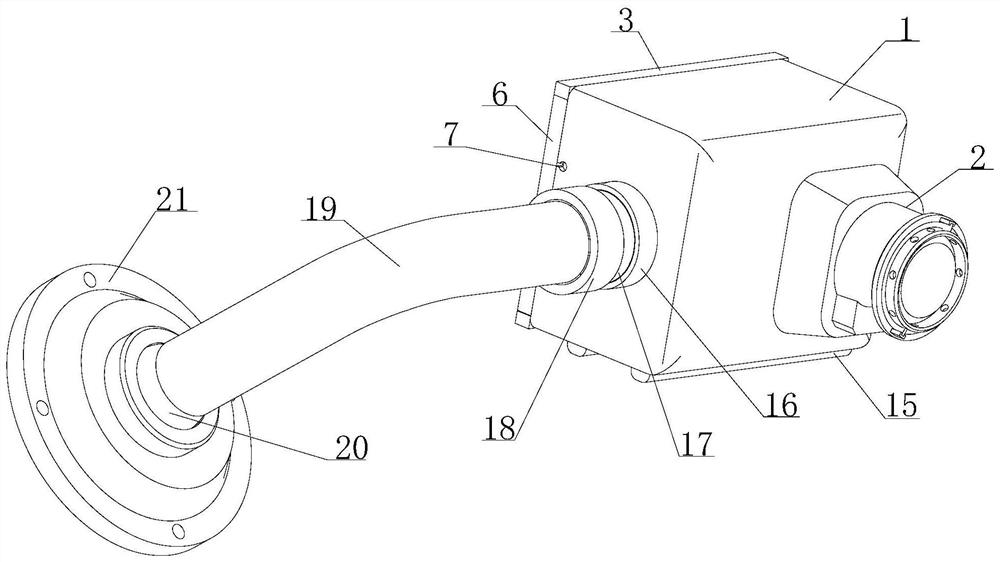
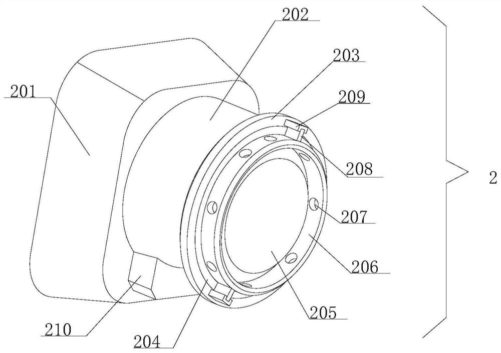
[0034] see Figure 1-2 , the present invention provides a technical solution: a monitoring device with protective measures for intelligent manufacturing, including a casing 1, the outer wall of the casing 1 is provided with a monitoring lens 2, and one end of the monitoring lens 2 is fixedly connected to the outer wall of the casing 1 , the inside of the monitoring lens 2 includes a fixed platform 201, one end of the fixed platform 201 is fixedly connected to the outer wall of the casing 1, the other end of the fixed platform 201 is provided with an outer lens barrel 202, and one end of the outer lens barrel 202 is connected to the outer wall of the fixed platform 201. The inner wall is fixedly connected, the outside of the outer lens barrel 202 is provided with an anti-collision ring 203, the inner wall of the anti-collision ring 203 is fixedly connected with the inner wall of the outer lens barrel 202, and the inner lens barrel 204 is arranged inside the outer lens barrel 202...
Embodiment 2
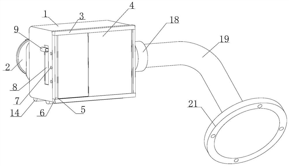
[0037] see Figure 1-4 , based on Embodiment 1, the present invention provides a technical solution: the end of the casing 1 away from the monitoring lens 2 is provided with a sliding door groove 3, the outer wall of the sliding door groove 3 is fixedly connected with the outer wall of the casing 1, and the sliding door groove 3 The inner wall is slidably connected with a sliding door 4, one end of the sliding door 4 is provided with a sealing strip 5, one end of the sealing strip 5 is fixedly connected with one end of the sliding door 4, the other end of the sealing strip 5 is fixedly installed with a frame strip 6, and the casing 1 The outer wall is provided with an outlet hole 17, the outer wall of the casing 1 is provided with a chute 8, the inner wall of the chute 8 is slidably connected with a slider, and the end of the slider far away from the chute 8 is fixedly installed with a wire harness 9, the casing 1 An inner door 10 is installed on the inner wall, and a screw ro...
Embodiment 3
[0040] see Figure 1-5 , based on Embodiment 1 and Embodiment 2, the present invention provides a technical solution: preferably, the bottom of the casing 1 is provided with an anti-collision strip 15, the outer wall of the anti-collision strip 15 is fixedly connected with the bottom of the casing 1, and the casing 1 is provided with a connecting cylinder 16, one end of the connecting cylinder 16 is fixedly connected with the outer wall of the casing 1, and the other end of the connecting cylinder 16 is provided with a rotating shaft 17, and the outer wall of the rotating shaft 17 is flexibly connected with the inner wall of the connecting cylinder 16 to rotate One end of the shaft 17 away from the connecting cylinder 16 is fixedly equipped with a connecting seat 18, and one end of the connecting seat 18 away from the rotating shaft 17 is provided with a connecting curved rod 19, and one end of the connecting curved rod 19 is fixedly connected with the outer wall of the connect...
PUM
 Abstract
Description
Claims
Application Information
 - R&D
- Intellectual Property
- Life Sciences
- Materials
- Tech Scout
- Unparalleled Data Quality
- Higher Quality Content
- 60% Fewer Hallucinations
Browse by: Latest US Patents, China's latest patents, Technical Efficacy Thesaurus, Application Domain, Technology Topic, Popular Technical Reports.
© 2025 PatSnap. All rights reserved.Legal|Privacy policy|Modern Slavery Act Transparency Statement|Sitemap|About US| Contact US: help@patsnap.com