Eureka AIR delivers breakthrough ideas for toughest innovation challenges, trusted by R&D personnel around the world.

Solar cell panel cleaning equipment

A technology for solar panels and cleaning equipment, applied in lighting and heating equipment, cleaning methods and appliances, cleaning methods using tools, etc., can solve problems such as inability to completely remove foreign objects, easy to damage battery panels, etc., and achieve flexible mobile equipment , no waste of water, the effect of secondary cleaning water

Inactive Publication Date: 2021-02-26
唐水连
View PDF0 Cites 0 Cited by
  • Summary
  • Abstract
  • Description
  • Claims
  • Application Information

AI Technical Summary

Problems solved by technology

[0004] In order to overcome the shortcomings of being unable to completely remove foreign matter and easily damaging the solar panel, the technical problem is to provide a solar panel that can remove sand and dust on the surface of the solar panel to a greater extent, protect the solar panel, and make it easier to clean the foreign matter. cleaning supplies

Method used


Image

  • Solar cell panel cleaning equipment
  • Solar cell panel cleaning equipment
  • Solar cell panel cleaning equipment

Examples


Embodiment 1

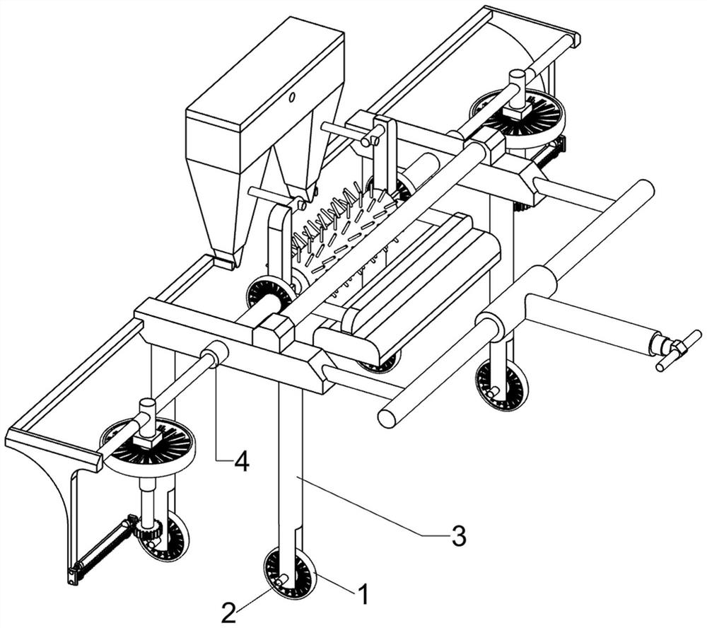
[0066]A solar panel cleaning equipment, such asfigure 1 As shown, it includes a first rotating wheel 1, a first rotating shaft 2, a moving mechanism 3, and a cleaning mechanism 4. The first rotating wheels 1 on the front, rear, left, and right are connected with a first rotating shaft 2, and the first rotating shaft 2 passes through the first rotating wheel. A moving mechanism 3 is rotatably connected between the wheel 1 and the first rotating shaft 2, and a cleaning mechanism 4 is rotatably connected between the moving mechanisms 3.

[0067]When the device needs to be used, the user can push the device to the solar panel that needs to be cleaned. At this time, the cleaning mechanism 4 is located on the upper side of the solar panel, pushing the device to drive the first runner 1 to rotate and move. The rotation of the wheel 1 drives the first shaft 2 to rotate in the moving mechanism 3, pushing the device to drive the moving mechanism 3 to move to the solar panel that needs to be clea...

Embodiment 2

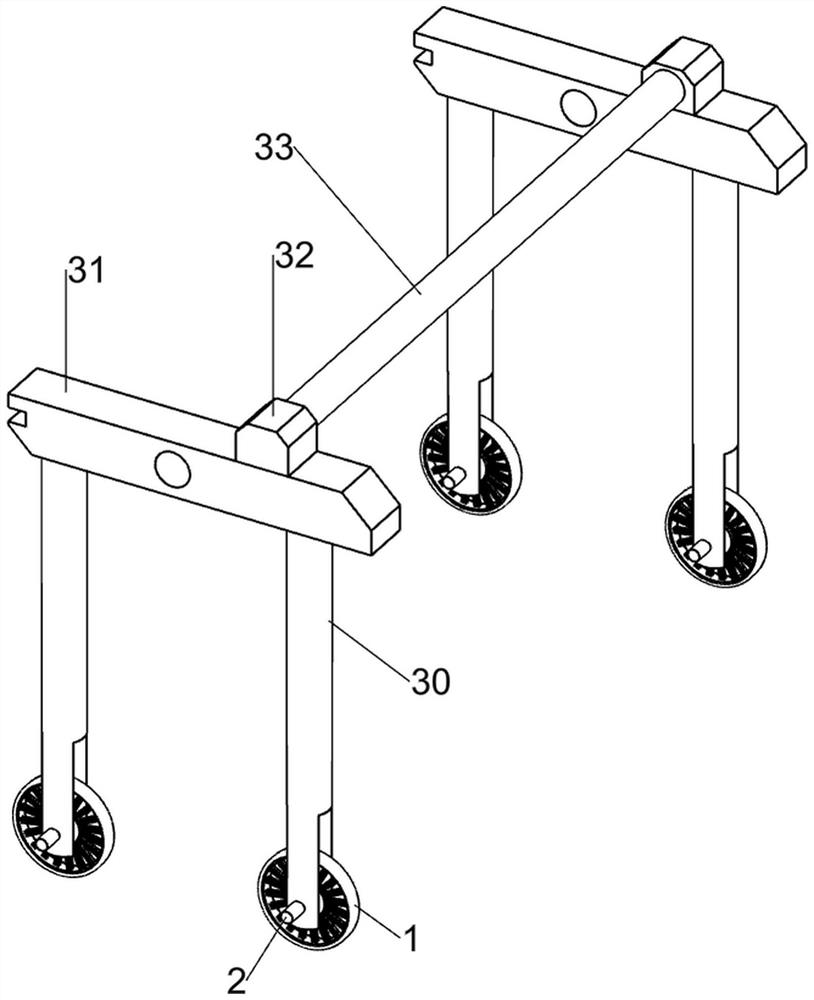
[0069]On the basis of Example 1, such asfigure 2 As shown, the moving mechanism 3 includes a supporting rod 30, a mounting block 31, a first fixed block 32, and a fixed rod 33. The first rotating shaft 2 is rotatably connected with the supporting rod 30, and the two supporting rods 30 on the front and rear sides are connected in a rotating manner. The mounting blocks 31 are connected to each other, the upper side of the mounting blocks 31 are connected to the first fixing block 32, and the fixing rod 33 is connected between the first fixing blocks 32.

[0070]When the first rotating wheel 1 rotates and moves, the first rotating shaft 2 is driven to rotate in the support rod 30, and then the support rod 30 is driven to move to the solar panel that needs to be cleaned. The movement of the support rod 30 drives the mounting block 31 to move, and the mounting block The movement of 31 drives the first fixed block 32 to move, and the movement of the first fixed block 32 drives the fixed rod ...


PUM


Abstract

The invention relates to cleaning equipment, particularly to solar cell panel cleaning equipment. A purpose of the invention is to provide solar cell panel cleaning equipment, which can remove dust and other foreign matter on the surface of a solar cell panel to a large extent, so that the cell panel is protected, and the foreign matter is easier to clean. According to the technical scheme, the solar cell panel cleaning equipment is characterized by comprising first rotating shafts, wherein first rotating wheels in four directions are connected with the first rotating shafts, and the first rotating shafts penetrate through the first rotating wheels; moving mechanisms rotationally connected between the first rotating shafts; and a cleaning mechanism rotatably connected between the moving mechanisms. Through cooperation of the supporting rod, the mounting block, the first fixing block and the fixing rod, the purpose of flexibly moving the equipment is achieved.

Description

Technical field[0001]The invention relates to a cleaning equipment, in particular to a solar cell panel cleaning equipment.Background technique[0002]Solar water heater as a kind of photoelectric equipment has entered every household. Because solar panels are installed outdoors, it is easy to accumulate dust and dirt on solar panels. If you do not remove the sand and dust on the panels in time And dirt, which will seriously affect its efficiency. The solar panel cleaning device can clean the surface of the solar panel, remove surface foreign matter, greatly improve the efficiency of the panel, and make more use of light energy. More power can be saved.[0003]However, the design of the existing solar panel cleaning device is not reasonable enough to completely remove foreign objects such as sand and dust on the surface of the solar panel, and it is easy to damage the solar panel. When the foreign objects are scraped off with a scraper, if they adhere to the solar panel, The foreign mat...

Claims


Application Information

Patent Timeline
IPC IPC(8): H02S40/10B08B1/04B08B3/00F26B5/16
CPCH02S40/10B08B3/00F26B5/16B08B1/32Y02E10/50
Inventor 唐水连
Owner 唐水连
Why Eureka
Eureka Blog
Learn More