Mechanical cleaning equipment
A technology for cleaning equipment and machinery, applied in the field of cleaning, can solve the problems of inability to recycle garbage, sweep the floor, and self-cleaning, etc., and achieve the effect of saving the time of disinfecting mops, being convenient to take, and easy to use.
- Summary
- Abstract
- Description
- Claims
- Application Information
AI Technical Summary
Problems solved by technology
Method used
Image

Examples
Embodiment 1
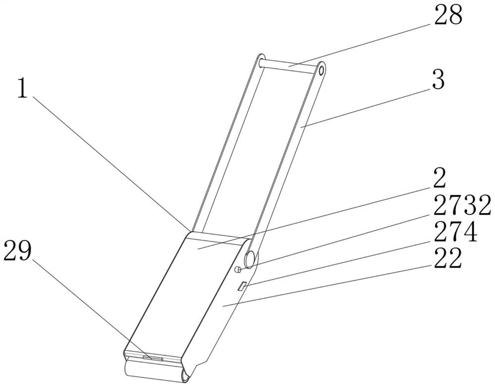
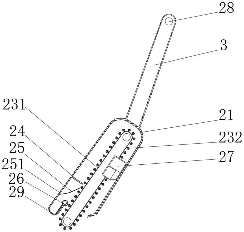
[0047] see Figure 1-2 , the present invention provides a technical solution: a mechanical cleaning device, including a cleaning device body 1 composed of a cleaning device 2 and a rod body 3, the cleaning device 2 includes a casing 21, and side plates 22 are fixedly connected to both sides of the casing 21, cleaning The inside of the device 2 is provided with a conveying mechanism 23, the left side of the conveying mechanism 23 is provided with a cleaning brush 24, the top of the cleaning brush 24 is fixedly connected with the inside of the housing 21, and the left bottom of the cleaning brush 24 is sequentially provided with a sliding ash plate 25 and The rolling mechanism 26, the top of the ash sliding board 25 is fixedly connected with the inside of the housing 21, the middle part of the ash sliding board 25 is provided with a sliding ash hole 251, the bottom of the inner wall of the housing 21 is fixedly connected with a cleaning device 27, and the conveying mechanism 23 i...
Embodiment 2
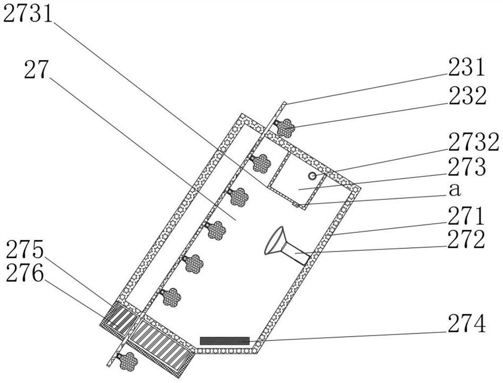
[0049] see Figure 1-4 On the basis of Embodiment 1, the present invention provides a technical solution: the cleaning device 27 includes a cleaning box 271, an ultrasonic oscillator 272 is fixedly connected to the right side of the inner wall of the cleaning box 271, and a sterilizer is fixedly connected to the top of the ultrasonic oscillator 272. Mechanism 273, the valve 274 is slidingly connected to the bottom of the cleaning box 271, the drying filter box 275 is fixedly connected to the outside of the bottom of the cleaning box 271, the inside of the drying filter box 275 is filled with desiccant 276, and the outside of the conveyor belt 231 runs through the cleaning box 271 in turn And dry filter box 275, sterilizing mechanism 273 includes sterilizing box 2731, the top of the right side of sterilizing box 2731 is fixedly connected with the inside of cleaning box 271, the right side of sterilizing box 2731 is fixedly connected with switch 2732, and the top of switch 2732 e...
Embodiment 3
[0051] see Figure 1-7, On the basis of Embodiment 1 and Embodiment 2, the present invention provides a technical solution: the cleaning device 232 includes a rubber body 2321, the inside of the rubber body 2321 is fixedly connected with a sponge body 2322, and the inside of the sponge body 2322 is provided with a water storage ball b, the bottom of the rubber body 2321 is fixedly connected with a rubber strip 2323, the bottom of the rubber strip 2323 extends to the inside of the conveyor belt 231 and is fixedly connected with the conveyor belt 231, the outer surface of the rubber body 2321 is fixedly connected with a cleaning strip c, the rubber body 2321 The inside of the water storage ball b includes a first elastic ring b1, the inner wall of the first elastic ring b1 is fixedly connected to the elastic block b2, and the bottom of the elastic block b2 is fixedly connected to the second elastic ring b3. An elastic ring b1 and a second elastic ring b3 form a cavity b4, the ca...
PUM
 Abstract
Description
Claims
Application Information
 - R&D
- Intellectual Property
- Life Sciences
- Materials
- Tech Scout
- Unparalleled Data Quality
- Higher Quality Content
- 60% Fewer Hallucinations
Browse by: Latest US Patents, China's latest patents, Technical Efficacy Thesaurus, Application Domain, Technology Topic, Popular Technical Reports.
© 2025 PatSnap. All rights reserved.Legal|Privacy policy|Modern Slavery Act Transparency Statement|Sitemap|About US| Contact US: help@patsnap.com