Stone crushing device for hydraulic engineering

A technology of crushing device and water conservancy engineering, applied in the direction of solid separation, filter screen, grid, etc., can solve the problems of reduced crushing efficiency, entry of gravel, low crushing efficiency, etc., and achieve the effect of improving crushing efficiency and avoiding clogging of the device.

Inactive Publication Date: 2021-03-02
朱化书
View PDF0 Cites 0 Cited by
  • Summary
  • Abstract
  • Description
  • Claims
  • Application Information

AI Technical Summary

Problems solved by technology

[0002] A large number of stones are used in the construction of water conservancy projects, and there are often some cracked and unusable bricks or large crushed stones. At present, these bricks or crushed stones are generally used as landfills. Buried in the recess for processing, but large pieces of crushed stone need to be crushed, the crushing efficiency of the existing crushing device is not high, at the same time, a large amount of crushed stone enters the crushing device, if the crushing device cannot be crushed in time, it will cause blockage, further reducing the Crushing efficiency

Method used


Image

  • Stone crushing device for hydraulic engineering
  • Stone crushing device for hydraulic engineering
  • Stone crushing device for hydraulic engineering

Examples


Embodiment 1

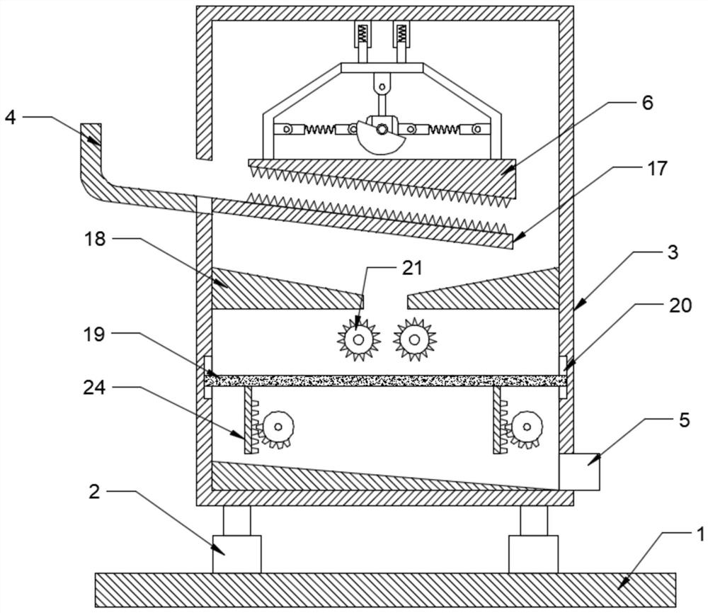
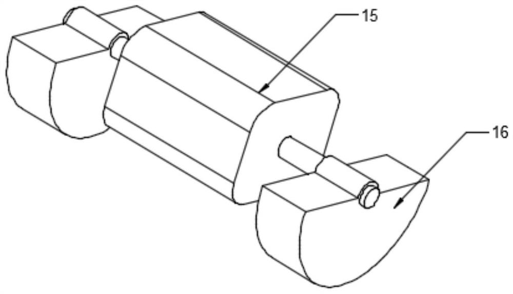
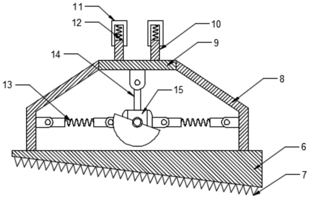
[0024] see Figure 1-4 , a stone crushing device for water conservancy projects, comprising a bottom plate 1 and a crushing box 3, a feed hopper 4 is connected to one side of the crushing box 3, a stone crushing assembly is arranged in the crushing box 3, and the stone crushing assembly The specific type is not limited. In this embodiment, preferably, the stone crushing assembly includes a vibrating plate 6, crushing teeth 7, a fixed frame 8, a fixed plate 9, a sleeve rod 10, a sleeve 11, a first damping spring 12, Connecting rod 14, biaxial motor 15, swing block 16 and extrusion plate 17, both swing blocks 16 are fan-shaped blocks and are symmetrically installed on the two output ends of biaxial motor 15, and the top of biaxial motor 15 is hinged by connecting rod 14 On the fixed plate 9, one end of a plurality of sleeve rods 11 is fixedly installed above the fixed plate 9, and the other end is movably sleeved in the sleeve 11 and a first damping spring 12 is arranged between...

Embodiment 2

[0032] In order to improve the crushing quality, this embodiment is further improved on the basis of Embodiment 1. The improvement is that a screening assembly is arranged under the crushing roller 21, and the specific type of the screening assembly is not limited. In this embodiment, preferably Yes, the screening assembly includes a sieve plate 19, a lift trough 20, a rack guide post 24, a rotating shaft 25, a transmission belt 26 and an incomplete gear 28, the lift trough 20 is set on the side wall of the crushing box 3, and the two ends of the sieve plate 19 are movably installed on the In the lifting groove 20, the rack guide post 24 is fixedly installed under the sieve plate 19 and intermittently cooperates with the incomplete gear 28. The incomplete gear 28 is fixedly installed on the rotating shaft 25, and the rotating shaft 25 is installed in the crushing box 3 in rotation. And one end extends to the outside of the crushing box 3 and is driven and connected with one of ...


PUM


Abstract

The invention discloses a stone crushing device for hydraulic engineering. The device comprises a bottom plate and a crushing box, wherein a feeding hopper is connected to one side of the crushing box, a stone crushing assembly is arranged in the crushing box, the stone crushing assembly comprises a vibration plate, crushing teeth, a fixing frame, a fixing plate, sleeve rods, sleeves, first damping springs, a connecting rod, a double-shaft motor, swing blocks and an extrusion plate, the two swing blocks are fan-shaped blocks and are symmetrically installed at the two output ends of the double-shaft motor, the top of the double-shaft motor is hinged to the fixing plate through a connecting rod, one ends of the plurality of sleeve rods are fixedly installed at the upper portion of the fixingplate, the other ends of the sleeve rods are movably arranged in the sleeves in a sleeved mode, the first damping springs are arranged between the other ends of the sleeve rods and the sleeves, the sleeves are arranged at the top of the crushing box, the vibration plate is installed below the swing blocks through the fixing frame, the extrusion plate is located below the feeding hopper and the vibration plate and fixed to the side wall of the crushing box, and the crushing teeth are fixedly arranged on the extrusion plate and the vibration plate. By arranging the crushing assembly, the crushing efficiency is improved, and the device is prevented from being blocked in the feeding process.

Description

technical field [0001] The invention relates to the field of water conservancy engineering, in particular to a stone crushing device for water conservancy engineering. Background technique [0002] A large number of stones are used in the construction of water conservancy projects, and there are often some cracked and unusable bricks or large crushed stones. At present, these bricks or crushed stones are generally used as landfills. Buried in the recess for processing, but large pieces of crushed stone need to be crushed, the crushing efficiency of the existing crushing device is not high, at the same time, a large amount of crushed stone enters the crushing device, if the crushing device cannot be crushed in time, it will cause blockage, further reducing the crushing efficiency. Contents of the invention [0003] The purpose of the present invention is to provide a stone crushing device for water conservancy engineering, so as to solve the problems raised in the above-me...

Claims


Application Information

Patent Timeline
IPC IPC(8): B02C1/12B02C4/08B02C23/16B02C23/02B07B1/34
CPCB02C1/12B02C4/08B02C23/02B02C23/16B07B1/343
Inventor 朱化书
Owner 朱化书
Why Eureka
Try Eureka