
Reactor flue gas pressure-relief treatment device in titanium sponge production process

A production process and processing device technology, applied in chemical instruments and methods, dispersed particle separation, separation methods, etc., can solve problems affecting the production environment, equipment and production site corrosion, reduce labor intensity, improve production environment quality, The effect of avoiding disorderly discharge

Inactive Publication Date: 2021-03-02
贵州兴钛新材料研究院有限公司
View PDF6 Cites 0 Cited by
  • Summary
  • Abstract
  • Description
  • Claims
  • Application Information

AI Technical Summary

Problems solved by technology

[0002] At present, the industrial production of sponge titanium mainly adopts the magnesium reduction titanium tetrachloride method. The production process is to continuously feed titanium tetrachloride into the closed reactor to react with liquid magnesium to form sponge titanium and magnesium chloride. Due to the specific gravity of the magnesium chloride liquid produced by the reaction is greater than liquid magnesium, so it settles to the bottom of the reactor. As the reduction reaction continues, the liquid magnesium level in the reactor rises continuously, and the pressure in the reactor will also gradually increase. In order to avoid overpressure in the reactor, the During the reduction production process, it is necessary to relieve the pressure of the reactor from time to time. In the prior art, a pressure relief pipe is usually provided on the large cover of the reactor, and the outlet is blocked with a silicone rubber plug. Remove the plug and release the pressure of the reactor. During the process of pressure relief, a large amount of flue gas will be discharged from the reactor. The main components of the flue gas include low-valent chlorides, titanium tetrachloride, etc. Attached to the lifting equipment of the factory building, it is easy to cause corrosion to the equipment and the production site, and seriously affects the production environment

Method used


Image

  • Reactor flue gas pressure-relief treatment device in titanium sponge production process

Examples


Embodiment Construction

[0013] The present invention will be described in further detail below in conjunction with accompanying drawing, but should not be interpreted as that the scope of the subject matter of the present invention is limited to following embodiment, under the situation of not departing from above-mentioned technical idea of ​​the present invention, all according to the common technical knowledge of this field and Various modifications, substitutions and alterations made by conventional means are included within the scope of the present invention.

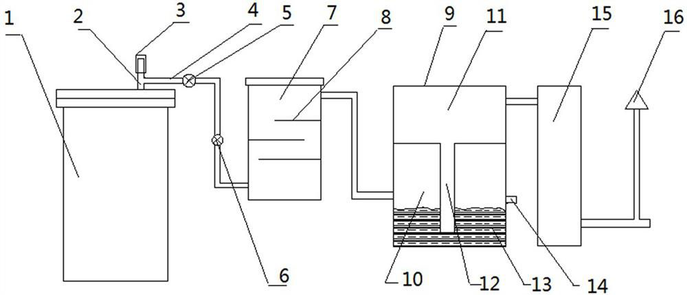
[0014] Such as figure 1 As shown, the reactor flue gas pressure relief treatment device in the production process of sponge titanium is mainly composed of a reactor 1 and a pressure relief pipe 2 on the large cover of the reactor. The top of the pressure relief pipe 2 is provided with a vacuum glue plug 3. It is characterized in that the pressure relief pipe 2 is connected to the buffer tank 7 through the pipeline 4, and the pipeline 4 is...


PUM


Abstract

The invention discloses a reactor flue gas pressure-relief treatment device in a titanium sponge production process, which mainly comprises a reactor and a pressure relief tube on a reactor large cover, wherein a vacuum rubber plug is arranged at the top end of the pressure relief tube, the pressure relief tube is connected to a buffer tank through a pipeline, a ball valve and a one-way valve aresequentially arranged on the pipeline, and the buffer tank, an acid seal tank, a leaching tower and a chimney are sequentially connected; a pressure relief area is arranged in the acid seal tank; upper and lower areas of an acid seal area are arranged in the acid seal tank and are in communication through a flow guide tube; the lower end of the flow guide tube is inserted into acid sealing liquidat the lower part of the acid seal area, and the position of a gas inlet in the acid seal tank is higher than the liquid level of the acid sealing liquid. The device can be utilized to realize automatic pressure relief of pressure in the reactor and flue gas collecting treatment, so that disordered discharge is avoided, production environment quality is improved, and labor intensity is reduced.

Description

technical field [0001] The invention belongs to the technical field of titanium sponge production, and in particular relates to a reactor flue gas pressure relief treatment device in the production process of titanium sponge. Background technique [0002] At present, the industrial production of sponge titanium mainly adopts the magnesium reduction titanium tetrachloride method. The production process is to continuously feed titanium tetrachloride into the closed reactor to react with liquid magnesium to form sponge titanium and magnesium chloride. Due to the specific gravity of the magnesium chloride liquid produced by the reaction is greater than liquid magnesium, so it settles to the bottom of the reactor. As the reduction reaction continues, the liquid magnesium level in the reactor rises continuously, and the pressure in the reactor will also gradually increase. In order to avoid overpressure in the reactor, the During the reduction production process, it is necessary t...

Claims


Application Information

Patent Timeline
Patent Type & Authority Applications(China)
IPC IPC(8): C22B34/12C22B5/04B01D45/04B01D53/75B01D53/78
CPCC22B34/1272C22B5/04B01D45/04B01D53/75B01D53/78
Inventor 王军袁继维李卫红徐展平
Owner 贵州兴钛新材料研究院有限公司
Learn More