Steam gas separation method

A separation method, a steam-gas technology, applied in the field of steam-gas separation, can solve the problem of low utilization rate of waste heat, achieve the effect of improving quality, increasing economic benefits, and avoiding disorderly discharge

Inactive Publication Date: 2018-12-11
TIANJIN BOCHANG ENERGY SAVING TECH DEV CO LTD
View PDF3 Cites 0 Cited by
  • Summary
  • Abstract
  • Description
  • Claims
  • Application Information

AI Technical Summary

Problems solved by technology

[0004] The purpose of the present invention is to provide a steam-gas separation method to solve the technical problem of low utilization rate of waste heat due to non-condensable gas impurities mixed with waste steam waste heat

Method used


Image

  • Steam gas separation method

Examples


Embodiment Construction

[0026] In order to make the purpose, technical solution and advantages of the present invention clearer, the technical solution of the present invention will be described in detail below. Apparently, the described embodiments are only some of the embodiments of the present invention, but not all of them. Based on the embodiments of the present invention, all other implementations obtained by persons of ordinary skill in the art without making creative efforts fall within the protection scope of the present invention.

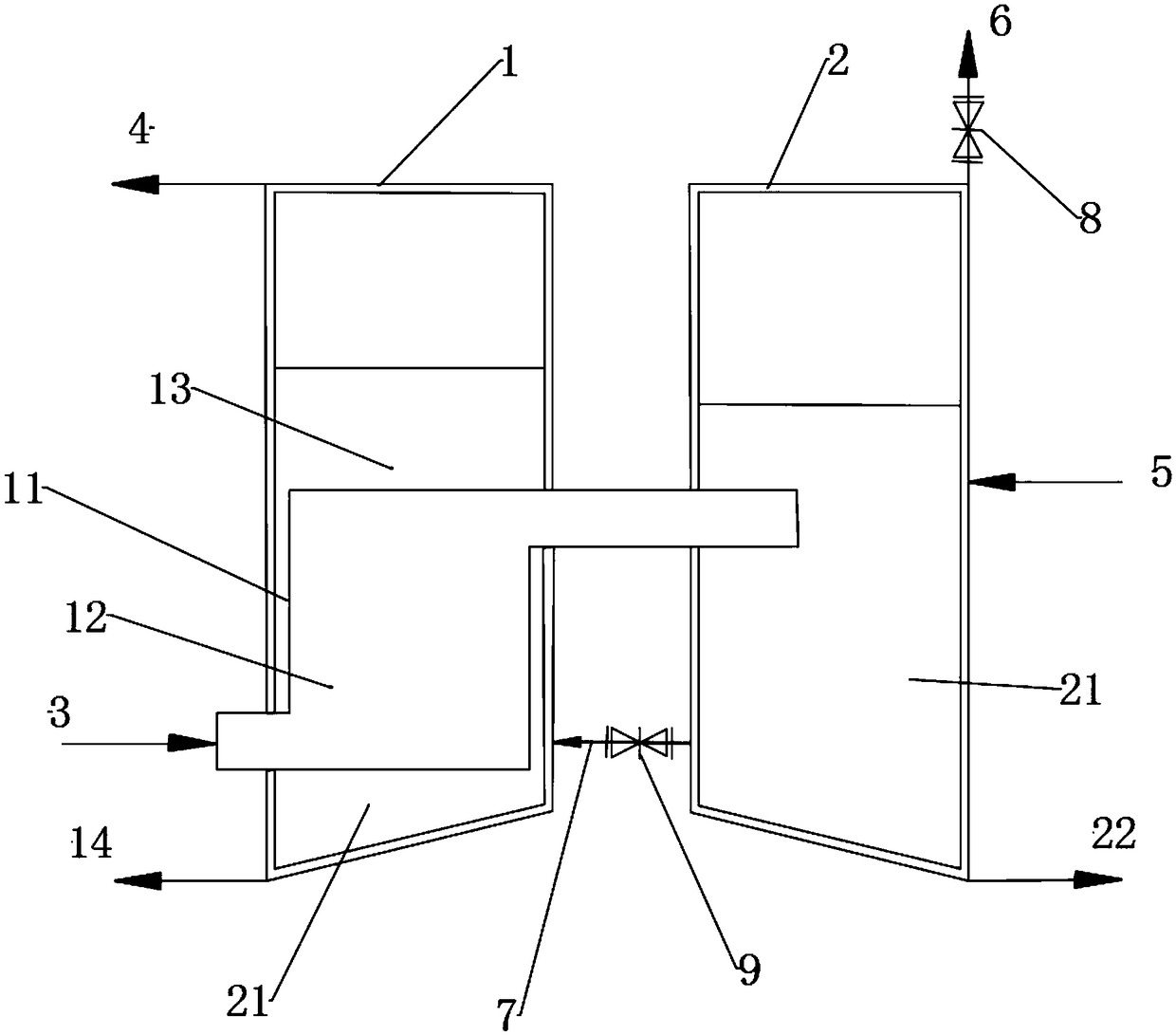
[0027] In describing the present invention, it is to be understood that the terms "central", "lateral", "length", "width", "height", "upper", "lower", "front", "rear", The orientation or positional relationship indicated by "left", "right", "vertical", "horizontal", "top", "bottom", "inner", "outer", "side" etc. is based on figure 1 The orientations or positional relationships shown are only for the convenience of describing the present invention and simplifyin...


PUM


Abstract

The invention provides a steam gas separation method, belongs to the technical field of steam gas separation, and solves the technical problem that in the prior art, waste steam is mixed with non-condensable gas impurities, and the utilization rate of waste heat is low. The method comprises the steps of: introducing a high-parameter steam-gas mixture into an evaporator, condensing into a gas-watermixture in a heat exchanger of the evaporator; introducing the gas-water mixture to be below a liquid level of a separator, discharging the non-condensable gas by a pressure limiting valve at the upper part of the separator, enabling liquid at the lower part of the separator to flow back to the evaporator through an external pipe, and supplying a low-parameter saturated steam subjected to the heating of the heat exchanger to outside. The method combining separation and backflow is adopted to separate the non-condensing gas impurities mixed in the waste steam residual heat to obtain pure steam, residual heat resources can be better utilized, the purposes of saving energy and increasing economic benefit are achieved, disorder emission of waste heat exhaust gas is avoid, the direction of residual heat utilization is expanded, white smoke is reduced, and the current policy requirements of white smoke elimination of the country are met.

Description

technical field [0001] The invention relates to the technical field of waste heat recovery, in particular to a steam-gas separation method. Background technique [0002] At present, waste heat includes waste heat of high-temperature exhaust gas, waste heat of cooling medium, waste heat of waste steam and waste water, waste heat of high-temperature products and slag, waste heat of chemical reactions, waste heat of combustible waste liquid and waste materials, and waste pressure of high-pressure fluid. According to the survey, the total waste heat resources of various industries It accounts for about 17%-67% of its total fuel consumption, and the recyclable waste heat resources are about 60% of the total waste heat resources. Therefore, waste heat recovery is widely used as an important way to improve energy economy and save fuel. field. [0003] The applicant found that the prior art has at least the following technical problems: In the field of waste heat utilization, there...

Claims


Application Information

Patent Timeline
Patent Type & Authority Applications(China)
IPC IPC(8): B01D5/00B01D53/00
CPCB01D5/00B01D53/002
Inventor 贾枭岳晓亮王海涛
Owner TIANJIN BOCHANG ENERGY SAVING TECH DEV CO LTD
Why Eureka
Try Eureka