Water body interactive mapping method and system

A technology for mapping and water bodies, applied in image analysis, image data processing, 3D image processing, etc.

Active Publication Date: 2021-03-02
SHANGHAI BILIBILI TECH CO LTD
View PDF10 Cites 3 Cited by
  • Summary
  • Abstract
  • Description
  • Claims
  • Application Information

AI Technical Summary

Problems solved by technology

[0004] The main purpose of this application is to propose a water body interactive mapping method, system, electronic device and computer-readable storage medium, aiming to solve how to solve the problem without relying on the number of vertices The problem of realizing the interaction effect of water body in the case of

Method used


Image

  • Water body interactive mapping method and system
  • Water body interactive mapping method and system
  • Water body interactive mapping method and system

Examples


Embodiment 1

[0072] Such as figure 2 As shown in FIG. 1 , it is a flow chart of a water body interactive mapping method proposed in the first embodiment of the present application. It can be understood that the flowchart in this method embodiment is not used to limit the sequence of execution steps.

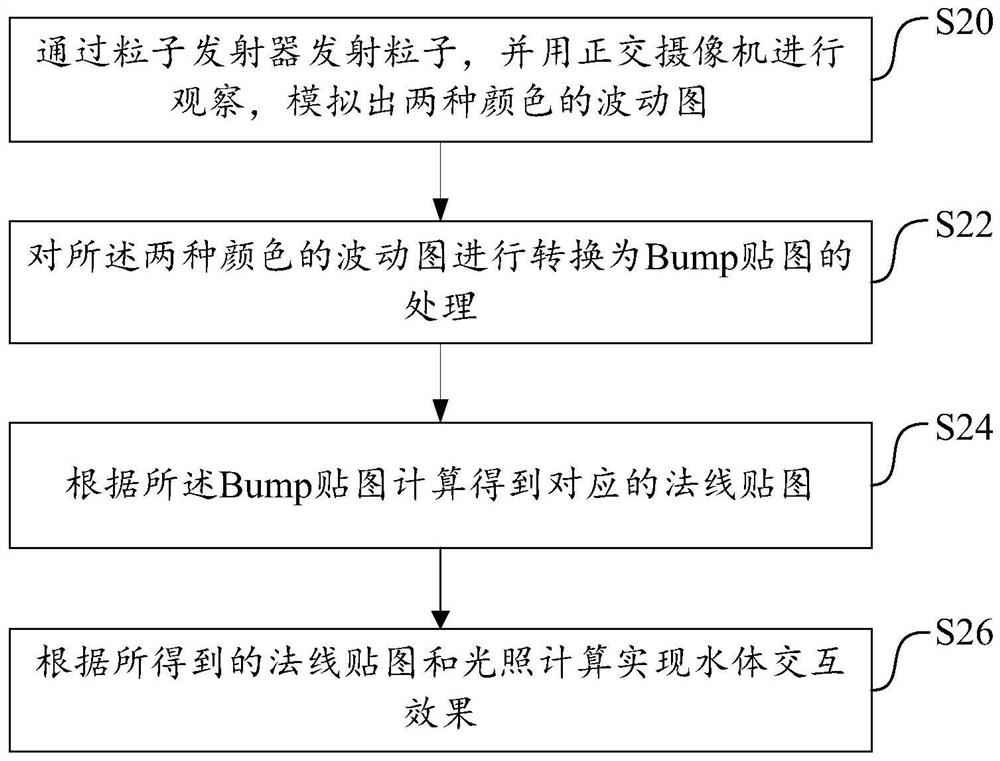
[0073] The method includes the following steps:

[0074] S20, emitting particles through a particle emitter, observing with an orthogonal camera, and simulating a wave pattern of two colors.

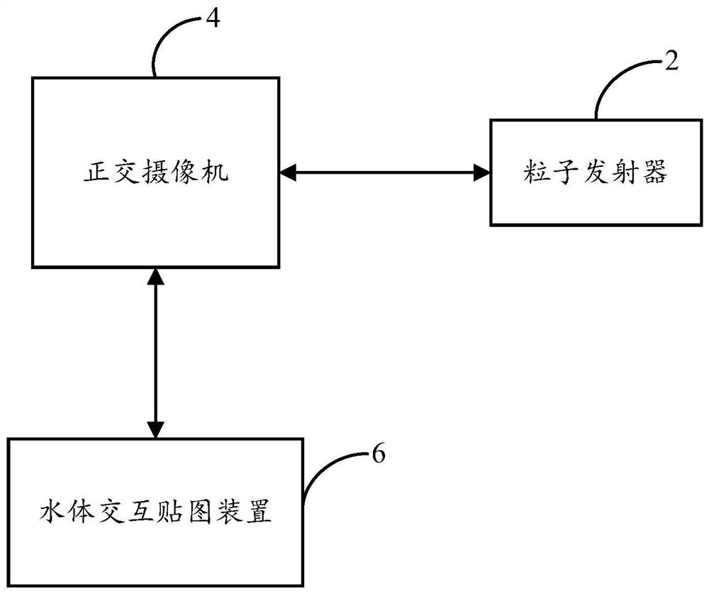
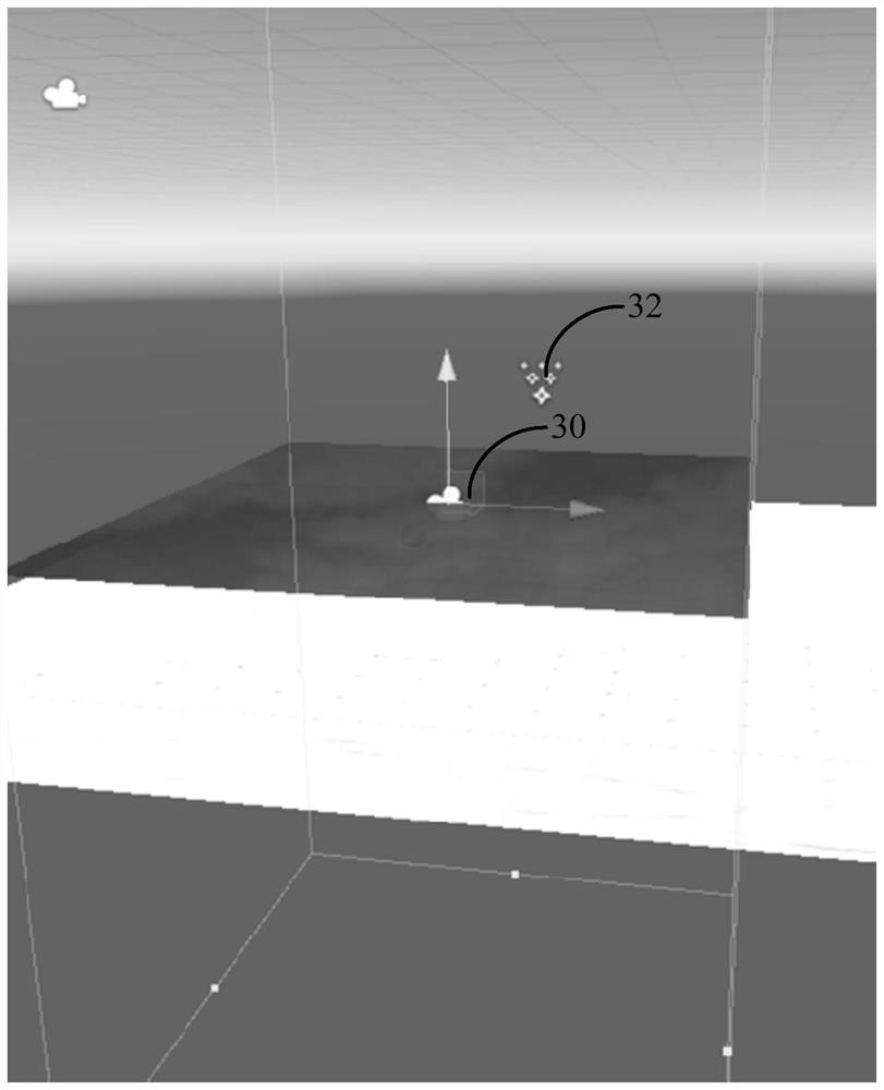
[0075] see further image 3 and Figure 4 , image 3 Schematic of the orthographic camera and particle emitter created for this example, Figure 4 It is a schematic diagram of the refinement process of the above step S20. In this embodiment, the step S20 specifically includes:

[0076] S200. Create an orthogonal camera and set a view observation level of the orthogonal camera.

[0077] Such as image 3 As shown, an orthographic camera 30 is created, and parameters such as the position of the o...

Embodiment 2

[0119] Such as Figure 14 As shown in FIG. 2 , it is a flow chart of a water body interactive mapping method proposed in the second embodiment of the present application. In the second embodiment, the water interactive mapping method further includes step S36 on the basis of the above-mentioned first embodiment. It can be understood that the flowchart in this method embodiment is not used to limit the sequence of execution steps.

[0120] The method includes the following steps:

[0121] S30, emitting particles through a particle emitter, observing with an orthogonal camera, and simulating a wave pattern of two colors.

[0122] For details of this step, refer to Figure 4 , Figure 5 and related descriptions will not be repeated here.

[0123] S32 , converting the fluctuation map of the two colors into a bump map. One of the colors indicates an increase in altitude, and the other color indicates a decrease in altitude.

[0124] In this embodiment, red color is selected ...

Embodiment 3

[0149] Such as Figure 18 As shown, it is a schematic diagram of a hardware architecture of an electronic device 20 proposed in the third embodiment of the present application. In this embodiment, the electronic device 20 may include, but is not limited to, a memory 21 , a processor 22 , and a network interface 23 that may be communicatively connected to each other through a system bus. It should be pointed out that, Figure 18 Only electronic device 20 is shown with components 21-23, but it should be understood that implementing all of the illustrated components is not a requirement and that more or fewer components may instead be implemented. In this embodiment, the electronic device 20 may be the water interactive mapping device 6 .

[0150] The memory 21 includes at least one type of readable storage medium, and the readable storage medium includes a flash memory, a hard disk, a multimedia card, a card-type memory (for example, SD or DX memory, etc.), random access memor...


PUM


Abstract

The invention discloses a water body interactive mapping method which comprises the following steps: emitting particles through a particle emitter, observing by using an orthogonal camera, and simulating fluctuation diagrams of two colors; converting the fluctuation diagrams of the two colors into a Bump map; calculating to obtain a corresponding normal map according to the Bump map; and realizinga water body interaction effect according to the obtained normal map and illumination calculation. The invention further discloses a water body interaction mapping system, an electronic device and acomputer readable storage medium. Therefore, vertex displacement calculation of traditional water body interaction can be replaced, and the water body interaction effect is achieved mainly through normal mapping calculation without depending on the number of vertexes.

Description

technical field [0001] The present application relates to the technical field of graphic processing, and in particular to a water body interactive mapping method, system, electronic device and computer-readable storage medium. Background technique [0002] In computer graphics processing technology, especially in the game development process, water body interaction is a common effect, mainly rendering the shape of the water surface when the water body interacts with objects, which is an important link that can show the details of the game. However, water body interaction is often a difficult point in water surface production technology. Traditional water body interaction effects are generally based on vertex movement, and the vertex displacement is calculated with the wave equation. This implementation method requires a high number of vertices and faces, and in the case of a low number of faces, it is impossible to simulate water bodies by modifying vertices. [0003] It s...

Claims


Application Information

Patent Timeline
Patent Type & Authority Applications(China)
IPC IPC(8): G06T7/90G06T15/55
CPCG06T7/90G06T15/55Y02A90/30
Inventor 杨意晨
Owner SHANGHAI BILIBILI TECH CO LTD
Why Eureka
Try Eureka