Transmission type electronic control terahertz antenna based on liquid crystal material

A liquid crystal material and terahertz technology, applied in antennas, antenna arrays, antenna grounding devices, etc., can solve the problems of limited beam scanning range and terahertz antenna feed source occlusion, etc., and achieve the effect of convenient processing and simple design scheme

Inactive Publication Date: 2021-03-02
HARBIN INST OF TECH
View PDF2 Cites 5 Cited by
  • Summary
  • Abstract
  • Description
  • Claims
  • Application Information

AI Technical Summary

Problems solved by technology

[0005] The present invention is aimed at the problem that the reflective liquid crystal electronically controlled terahertz antenna feed source is...

Method used


Image

  • Transmission type electronic control terahertz antenna based on liquid crystal material
  • Transmission type electronic control terahertz antenna based on liquid crystal material
  • Transmission type electronic control terahertz antenna based on liquid crystal material

Examples


specific Embodiment 1

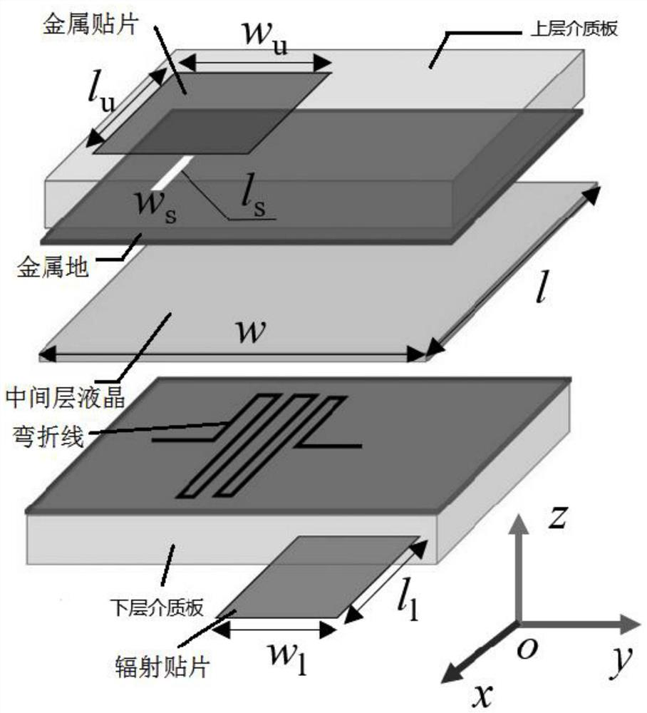
[0022] according to Figure 1 to Figure 5 As shown, the present invention provides a transmissive electronically controlled terahertz antenna based on liquid crystal materials, a transmissive electronically controlled terahertz antenna based on liquid crystal materials, and the terahertz antenna includes: an upper dielectric plate, a metal patch, a metal Ground, middle layer liquid crystal, bending line, radiation patch and lower dielectric board;

[0023] The metal patch and the metal ground are respectively etched on the upper surface and the lower surface of the upper dielectric board, the metal ground structure etches a slit structure, and the middle layer liquid crystal is encapsulated between the upper dielectric board and the lower dielectric board, and the curved The folding line is processed on the upper surface of the lower dielectric board, and the radiation patch is etched on the lower surface of the lower dielectric board.

[0024] The size of the gap structure i...

specific Embodiment 2

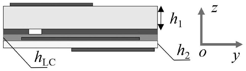
[0030] The structure of the transmissive liquid crystal electronically controlled terahertz antenna unit designed by the present invention is as follows: Figure 1-Figure 3 As shown, it can be seen that the unit structure is composed of an upper layer slot-coupled microstrip antenna, a middle layer liquid crystal, and a lower layer microstrip antenna. The upper slot-coupled microstrip antenna is composed of an upper dielectric plate, a metal patch, and a metal ground, and the lower layer microstrip antenna is composed of a lower dielectric plate, a bending line, and a radiation patch; among them, the metal patch and metal patch of the upper slot-coupled microstrip antenna The ground structures are respectively etched in the thickness h 1 The upper medium plate and the lower surface. By etching size w in the metal ground structure s × l s (value range: 0.01λ 0 ≤w s ≤0.02λ 0 and 0.25λ 0 ≤l s ≤0.35λ 0 ) gap structure to realize the coupling of the electromagnetic wave en...


PUM


Abstract

The invention relates to a transmission type electronic control terahertz antenna based on a liquid crystal material. The invention belongs to the technical field of microwave device engineering. A terahertz antenna comprises an upper dielectric plate, a metal patch, a metal ground, a middle liquid crystal layer, a bending line, a radiation patch and a lower dielectric plate. The metal patch and the metal ground are respectively etched on the upper surface and the lower surface of the upper layer dielectric plate, a gap structure is etched in the metal ground structure, the middle layer liquidcrystal is packaged between the upper layer dielectric plate and the lower layer dielectric plate, the bending line is processed on the upper surface of the lower layer dielectric plate, and the radiation patch is etched on the lower surface of the lower layer dielectric plate. Due to the fact that the incident wave and the reflected wave are located on the two sides of the array, the problem that the feed source horn antenna is shielded is effectively solved.

Description

technical field [0001] The invention relates to the technical field of microwave device engineering, and relates to a transmissive electronically controlled terahertz antenna based on liquid crystal materials. Background technique [0002] With the vigorous development of terahertz technology, electronically controlled terahertz antenna arrays with beam scanning function are widely used in radar detection, imaging systems and wireless communications. The existing electronically controlled terahertz antenna array mainly uses graphene or liquid crystal materials in the structure to realize the control of the beam of the antenna array. The advantage of graphene material is that it has high tuning rate and low dielectric loss. However, limited by the preparation process, the current high-purity graphene is difficult to produce in large areas, and the conductivity of graphene has strong dispersion characteristics. These problems limit the promotion of graphene in terahertz anten...

Claims


Application Information

Patent Timeline
IPC IPC(8): H01Q1/38H01Q1/48H01Q15/14H01Q21/00
CPCH01Q1/38H01Q1/48H01Q15/145H01Q21/00
Inventor 孟繁义丁畅
Owner HARBIN INST OF TECH
Why Eureka
Try Eureka