Permanent magnet motor and oil pumping device using the permanent magnet motor

A technology for permanent magnet motors and components, applied in electromechanical devices, synchronous motors with stationary armatures and rotating magnets, magnetic circuits, etc. structure and other issues, to achieve the effect of high reliability and stable structure

Active Publication Date: 2021-06-29
瑞昌市森奥达科技有限公司
View PDF2 Cites 0 Cited by
  • Summary
  • Abstract
  • Description
  • Claims
  • Application Information

AI Technical Summary

Problems solved by technology

And this type of permanent magnet motor can be used in pumping units, and its structure is more compact compared with high-speed motors. Refer to the direct traction type pumping unit of the external rotor motor of CN101696624A, but this patent does not disclose the specific structure of its permanent magnet motor
According to the existing technology, the working environment of the oil pumping unit is harsh, and the structure of the outer rotor makes the rotor more susceptible to external influences
The existing permanent magnet motor is difficult to meet the needs, it is necessary to provide a permanent magnet motor with a more reliable structure, which is specially used in the oil pumping unit

Method used


Image

  • Permanent magnet motor and oil pumping device using the permanent magnet motor
  • Permanent magnet motor and oil pumping device using the permanent magnet motor
  • Permanent magnet motor and oil pumping device using the permanent magnet motor

Examples


Embodiment Construction

[0028] In order to make the purpose, technical solutions and advantages of the embodiments of the present invention more clear, the technical solutions in the embodiments of the present invention will be clearly and completely described below in conjunction with the drawings in the embodiments of the present invention.

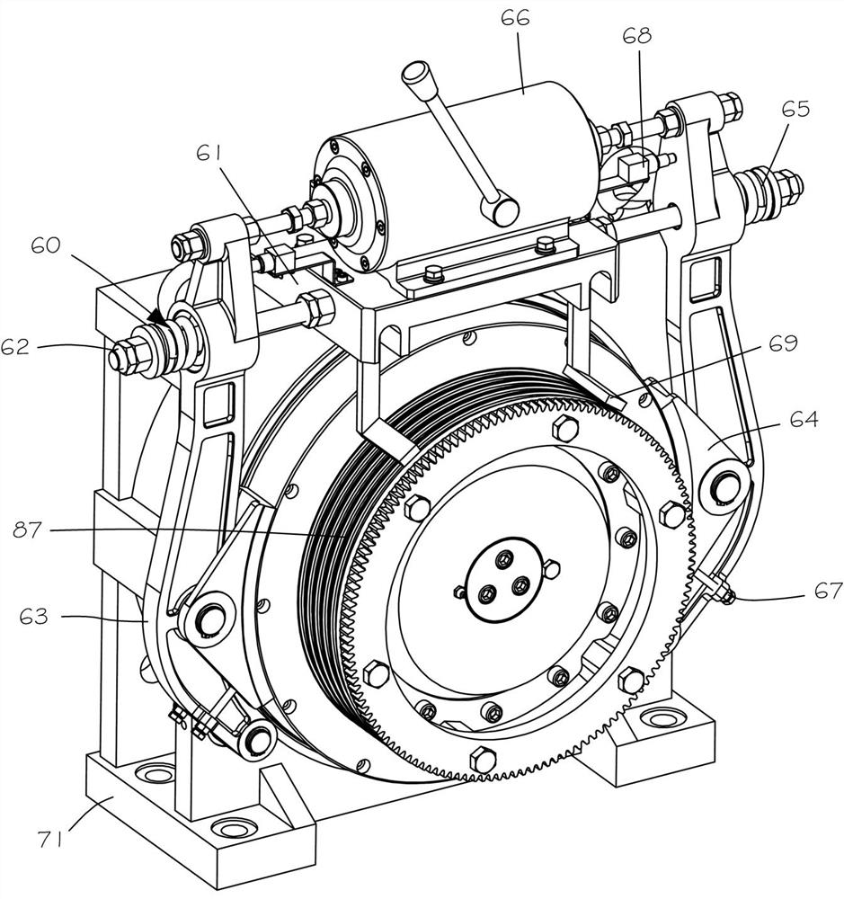
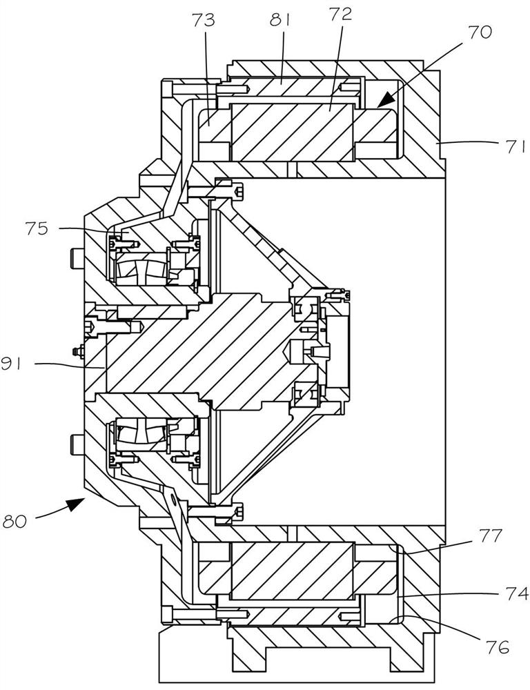
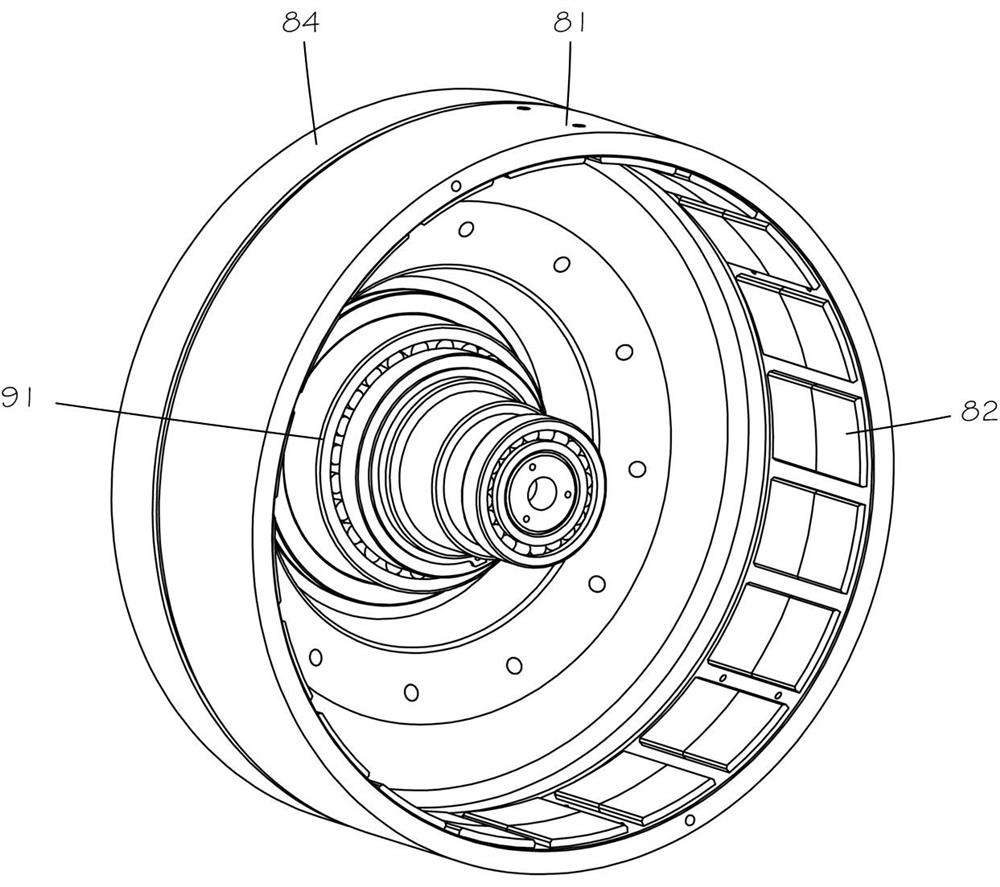
[0029] Such as Figures 1 to 6 The shown permanent magnet motor 11 of the present invention includes a stator assembly 70 , a rotor assembly 80 , and a braking assembly 60 . The stator assembly 70 includes a housing 71 , a stator core 72 , and a stator winding 73 . The housing 71 has a coaxial annular groove 74 and a support column 75 . The annular groove 74 has a large-diameter wall surface 76 and a small-diameter wall surface 77 , and the small-diameter wall surface 77 is the outer surface of the support column 75 . The stator core 72 is sleeved on the support column 75 , and the stator winding 73 is installed on the stator core 72 . An alternating magnet...


PUM


Abstract

The invention discloses a permanent magnet motor, which is characterized by comprising a stator assembly, a rotor assembly and a brake assembly. The rotor assembly includes spokes, multiple magnets, silicon steel sheets, hub, end rings, and bars. The spokes are fixed on the side wall of the annular groove, and the silicon steel sheets are installed in the spokes. The silicon steel sheet has multiple first grooves and second grooves, the guide bars are installed in the first grooves, and the magnets are installed in the second grooves. The wheel hub is fixed on one end of the spoke, and the wheel hub is installed to the inner surface of the supporting column through a rotating shaft. The end rings are located on both sides of the silicon steel sheet, the spokes have oblique holes, and a positioning column extends into the end ring from the oblique holes and squeezes the end rings at least partially into the silicon steel sheets. The permanent magnet motor of the present invention adopts the outer rotor permanent magnet synchronous motor structure, has multiple pairs of magnets, and can realize low-speed and high-torque rotation. The positioning column squeezes the silicon steel sheet while fixing the end ring to keep the silicon steel sheet in a compressed state.

Description

technical field [0001] The invention belongs to the application technology of a permanent magnet motor, in particular to a permanent magnet motor and an oil pump using the permanent magnet motor. Background technique [0002] It is known in the prior art that the multi-slot and multi-pole structure can be used to manufacture permanent magnet motors, such as CN110061592A and the like. And this type of permanent magnet motor can be used in pumping units, and its structure is more compact compared with high-speed motors. Refer to the direct traction type pumping unit of the external rotor motor of CN101696624A, but this patent does not disclose the specific structure of its permanent magnet motor . According to the prior art, the working environment of the oil pumping device is harsh, and the structure of the outer rotor makes the rotor more susceptible to external influences. The existing permanent magnet motor is difficult to meet the needs, and it is necessary to provide a...

Claims


Application Information

Patent Timeline
Patent Type & Authority Patents(China)
IPC IPC(8): H02K1/27H02K1/28H02K1/22H02K1/26H02K1/30H02K7/10H02K21/22H02K21/46
CPCH02K1/223H02K1/26H02K1/2786H02K1/28H02K1/30H02K7/10H02K21/22H02K21/46
Inventor 王贤长
Owner 瑞昌市森奥达科技有限公司
Why Eureka
Try Eureka