
Adjustable bidirectional linkage combined tool

A two-way linkage and combined tool technology, applied in the direction of manufacturing tools, hand-held tools, etc., can solve problems such as the inability to quickly remove screws, achieve the effects of enhancing safe operation and safe maintenance, improving power supply reliability, and avoiding irregular operations

Active Publication Date: 2021-03-05
GUIZHOU POWER GRID CO LTD
View PDF5 Cites 0 Cited by
  • Summary
  • Abstract
  • Description
  • Claims
  • Application Information

AI Technical Summary

Problems solved by technology

[0004] In view of the problem that the above-mentioned existing adjustable two-way linkage combination tool cannot quickly remove the screw, the present invention is proposed

Method used


Image

  • Adjustable bidirectional linkage combined tool
  • Adjustable bidirectional linkage combined tool
  • Adjustable bidirectional linkage combined tool

Examples


Embodiment 1

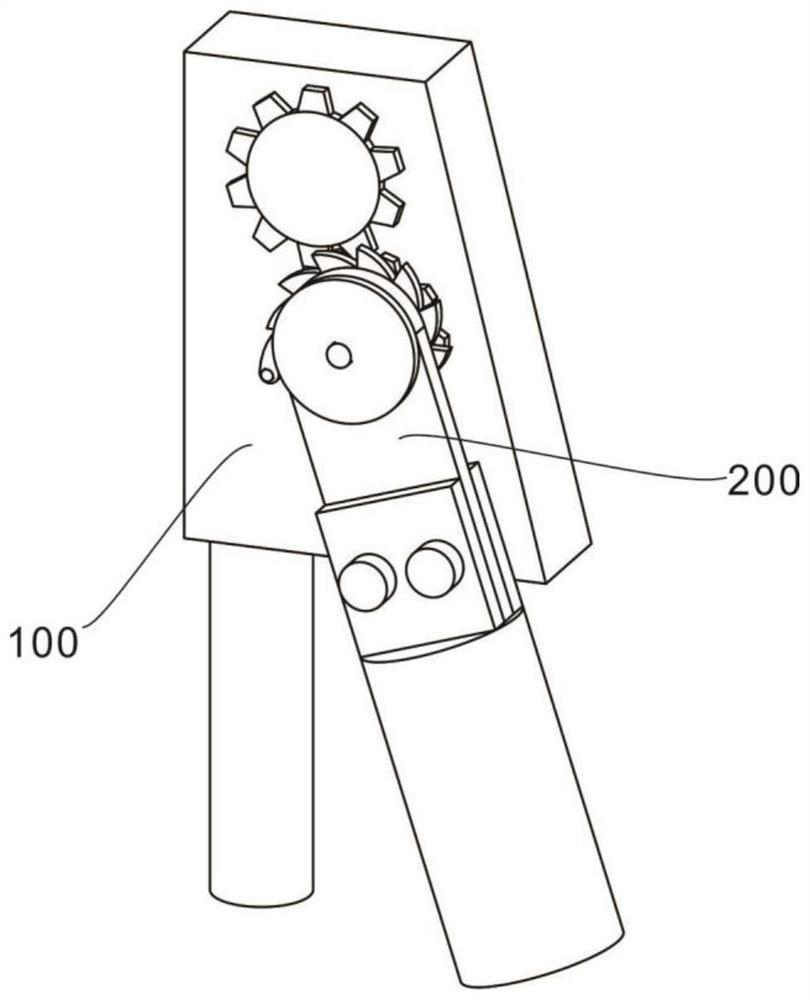
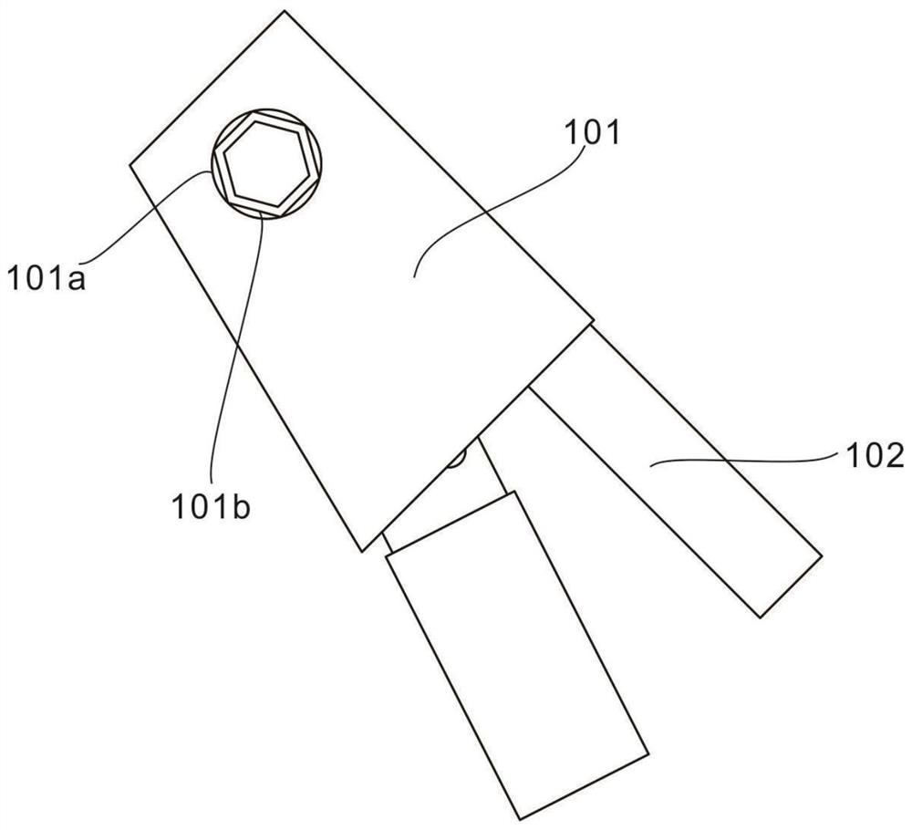
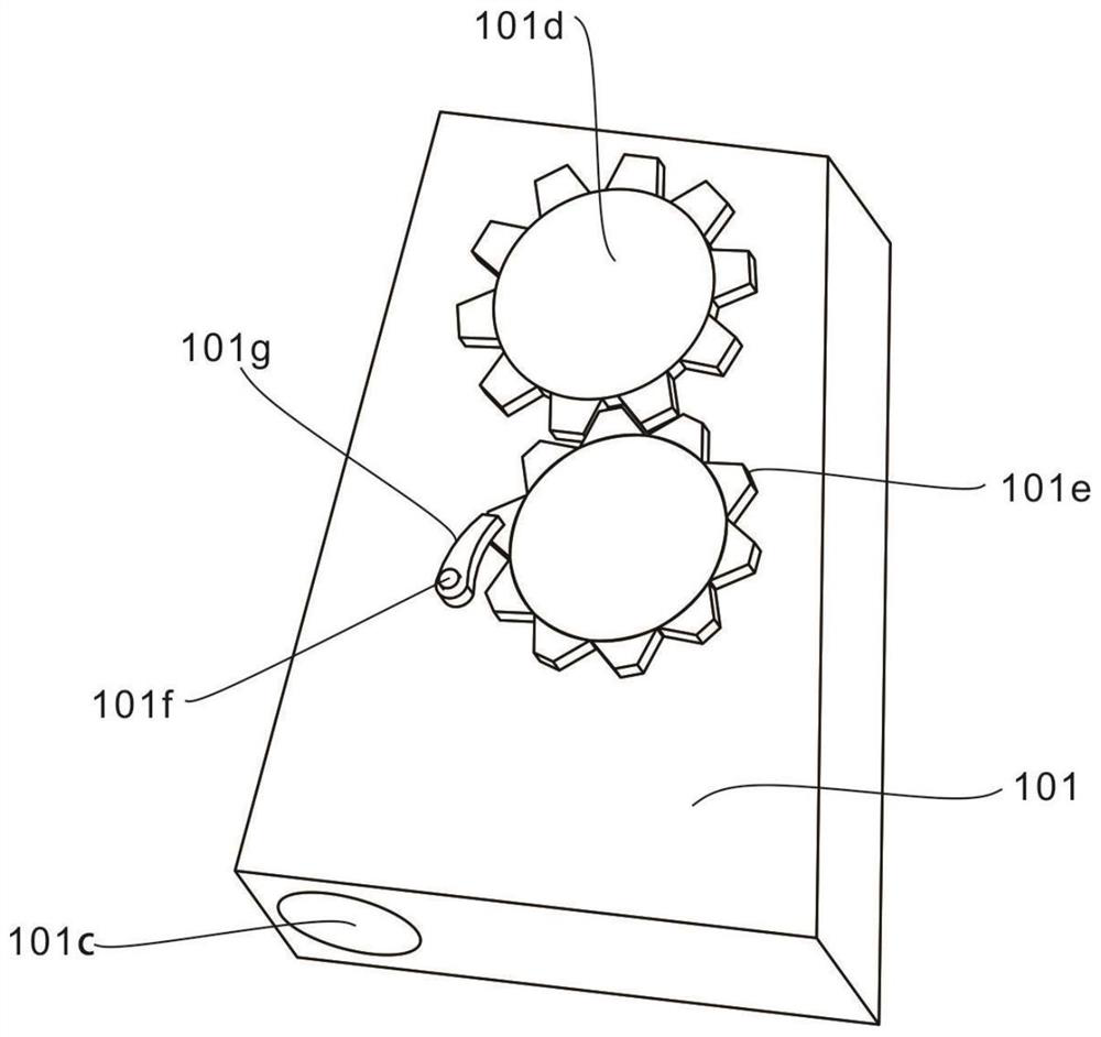
[0028] refer to Figure 1-5 , provides a schematic diagram of the overall structure of an adjustable two-way linkage combination tool, such as Figure 1-5 , an adjustable two-way linkage combination tool includes a card and assembly 100 for limiting the screw, a base 101 for bearing and limiting, a handle 102 for limiting the base 101, and a transmission that provides power for unscrewing the screw. The assembly 200 and the mounting block 201 for carrying and connecting, the limiting hole 101a and the limiting sleeve 101b for limiting the screw, the first threaded hole 101c for connecting the base 101 and the handle 102, and power transmission The first transmission tooth 101d and the second transmission tooth 101e, the first limit rod 101f that limits the brake pawl 101g, and the brake pawl 101g that limits the transmission assembly 200; The limit sleeve 101b located in the limit hole 101a in the component 100 limits the screw, and then the power is provided by the transmiss...

Embodiment 2

[0031] refer to Figure 4-5 , this embodiment is different from the first embodiment in that: the transmission assembly 200 that provides power for unscrewing the screw also includes a rotating shaft 202 that drives the transmission assembly 200 to rotate, drives the card and the second transmission tooth 101e in the assembly 100 to rotate The ratchet 203, the limit block 204 that limits the mounting block 201, the second limit lever 201a that limits the driving pawl 201b, the driving pawl 201b that drives the ratchet 203, and fixes the mounting block 201 The fixing block 205, the second threaded hole 205a and the screw 205b that fix the mounting block 201, and the pressing block 206 that drives the mounting block 201 to rotate, the present invention is located in the limiting hole 101a through the set card and assembly 100. The position sleeve 101b limits the screw, and then presses the pressing block 206 in the transmission assembly 200, so that the pressing block 206 drives...


PUM


Abstract

The invention discloses an adjustable bidirectional linkage combination tool. The adjustable bidirectional linkage combination tool comprises a clamping assembly and a transmission assembly, wherein the clamping assembly comprises a base and a grip located at one side of the base; and the transmission assembly comprises a mounting block, and the mounting block is located at the top of the base. According to the adjustable bidirectional linkage combination tool, through cooperation of the clamping assembly and the transmission assembly, an operator can rapidly assemble and disassemble screws when replacing and installing various meters and devices, screw assembling and disassembling work can be completed more conveniently and safely, workers can be rapidly put into electric power work corresponding to the workers, and the problems of non-standard traditional operation, high time cost and low working efficiency are solved; the safety operation stability of primary equipment is improved,and the working efficiency and the working quality are improved; and therefore, safe operation and safe maintenance of power grid equipment are effectively enhanced through on-site improvement, and power supply reliability of a power grid is improved.

Description

technical field [0001] The invention relates to the technical field of hand tools, in particular to an adjustable two-way linkage combination tool. Background technique [0002] In recent years, when replacing and maintaining equipment in the power grid, a wrench is often used to disassemble the screws. However, when the site for replacing and installing equipment is too narrow, the staff cannot twist the screws with a conventional wrench, or when twisting the nut You can only perform simple operations with one hand, and you can’t fix the gasket on the back, so you can’t unscrew the screws, and you can’t work smoothly. Moreover, the old equipment or meters have been installed for too long. When twisting the nut, the screw and the washer are stuck together, and the corresponding washer at the back rotates in the same direction, so that it cannot be removed quickly with ordinary tools. Contents of the invention [0003] The purpose of this section is to outline some aspects...

Claims


Application Information

Patent Timeline
Patent Type & Authority Applications(China)
IPC IPC(8): B25B27/14
CPCB25B27/14
Inventor 刘栖张霖薛静杨超杨俊秋康婕瀅靳斌吴冕之李俊文王珺郭天昀陈湫林
Owner GUIZHOU POWER GRID CO LTD
Learn More