
Compact speed reducer with independent lubrication sealing cavity

A sealed cavity, compact technology, applied in the direction of gear lubrication/cooling, belt/chain/gear, transmission parts, etc., can solve the problems of shortened service life, aging of internal parts, temperature rise, etc. Risk, lubricating effect improvement, oil temperature reduction effect

Pending Publication Date: 2021-03-05
ZHEJIANG TONGLI HEAVY GEAR
View PDF0 Cites 0 Cited by
  • Summary
  • Abstract
  • Description
  • Claims
  • Application Information

AI Technical Summary

Problems solved by technology

[0003] Now take the reducer acting in the mixing equipment as an example. The motor of the reducer and the reducer mechanism are arranged in parallel, installed vertically, and the output is set downward, which can meet the mixing requirements of the reducer. However, the requirements for the reducer of the mixing equipment are "It has the characteristics of small speed ratio, fast speed, compact structure, temperature rise of the reducer, and sensitivity to oil leakage." However, the existing reducer often has the following two problems. One is that the temperature rise is too high, which will lead to The internal parts are aging, which shortens the service life. The second is oil leakage. Once the above phenomenon occurs, it will be inconvenient to maintain because the shaft of the reducer is not easy to replace, and the maintenance cost is high, which will bring great inconvenience to users.

Method used


Image

  • Compact speed reducer with independent lubrication sealing cavity
  • Compact speed reducer with independent lubrication sealing cavity
  • Compact speed reducer with independent lubrication sealing cavity

Examples


Embodiment Construction

[0029] The following will clearly and completely describe the technical solutions in the embodiments of the present invention with reference to the accompanying drawings in the embodiments of the present invention. Obviously, the described embodiments are only some, not all, embodiments of the present invention. Based on the embodiments of the present invention, all other embodiments obtained by persons of ordinary skill in the art without making creative efforts belong to the protection scope of the present invention.

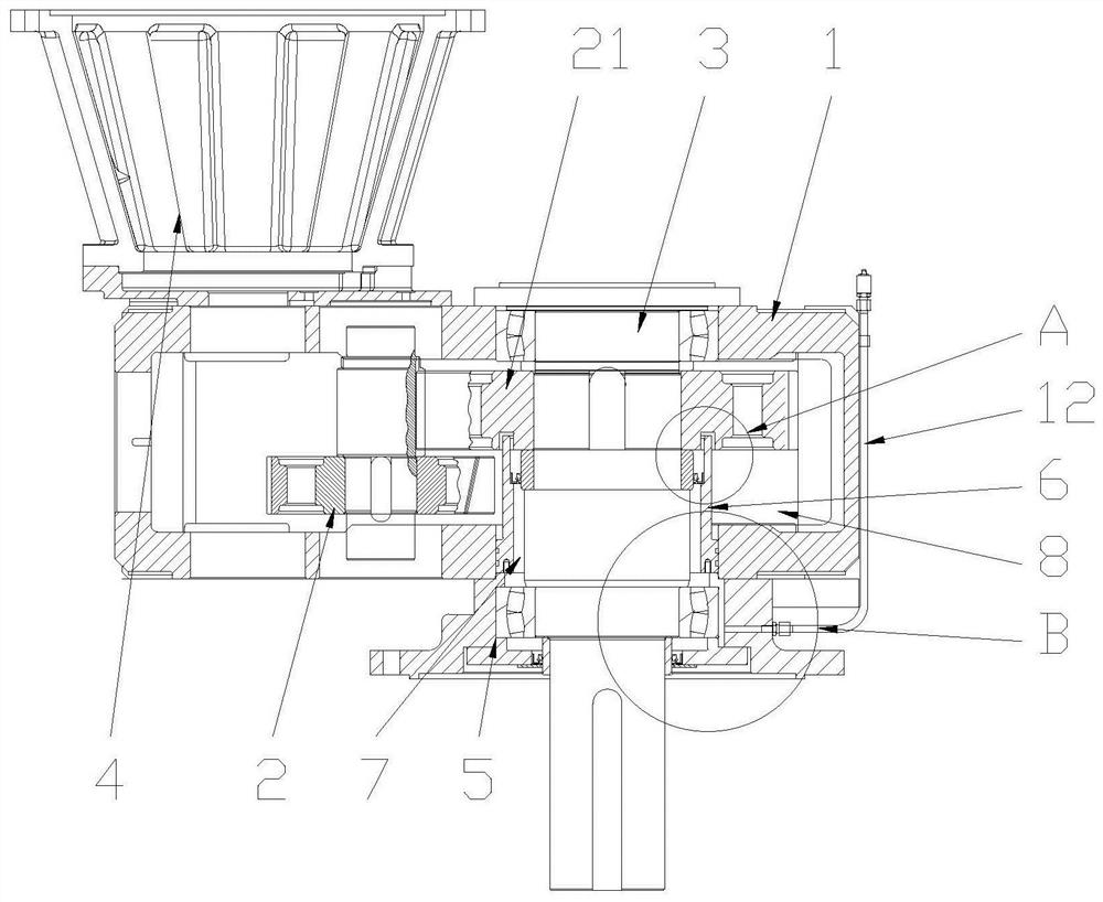
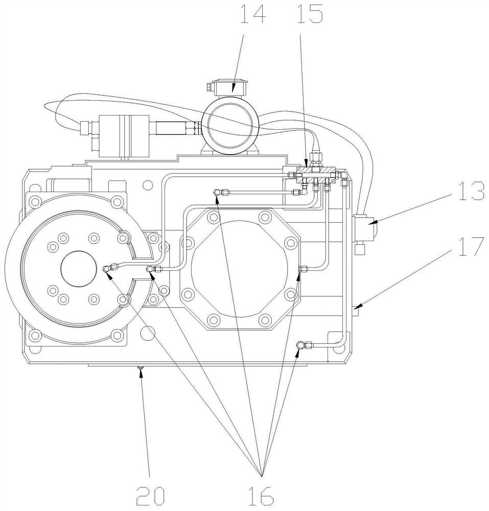
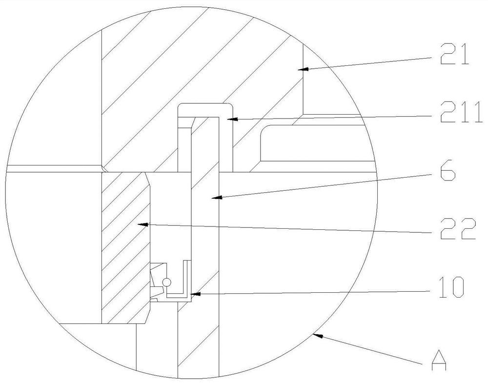
[0030] Such as Figures 1 to 4 A compact speed reducer with an independent lubricating and sealing chamber shown includes a case body 1, a gear set 2 set in the case body 1, and an output shaft 3 linked with the gear set 2. The upper part of the case body 1 is provided with There is a support 4, the lower part of the box body 1 is provided with an output shaft linkage hole 5 that can be linked with the output shaft 3, a bearing assembly is provided between the...


PUM


Abstract

The invention relates to compact speed reducer with an independent lubrication sealing cavity. The compact speed reducer comprises a box body, a gear set, an output shaft, a support, an output shaft linkage hole, a bearing assembly and a sealing mechanism, and is characterized in that a sealing spacer bush arranged on the periphery of the output shaft in a sleeved mode is arranged at the position,located in the middle of the output shaft linkage hole, of the box body; a first lubrication sealing cavity is arranged between the sealing spacer bush and the output shaft; a second lubrication sealing cavity is arranged between the sealing spacer bush and the box body; an O-shaped ring located between the box body and the sealing spacer bush is embedded in one end of the sealing spacer bush; and a first oil seal located between the output shaft and the sealing spacer bush is arranged at the other end of the sealing spacer bush. The compact speed reducer with the independent lubrication sealing cavity provided by the invention has the beneficial effects that the lubrication effect is good, the vertical installation stirring function can be achieved, the sealing performance is reliable, the transmission efficiency is high, and the bearing capacity is high.

Description

technical field [0001] The invention relates to the technical field of reducer equipment, in particular to a compact reducer with an independent lubricating and sealing chamber. Background technique [0002] The reducer is an independent component composed of gear transmission, worm transmission, gear and worm transmission enclosed in a rigid shell, and is often used as a reduction transmission device between the original moving part and the working machine. It plays the role of matching speed and transmitting torque between prime mover and working machine or actuator, and is widely used in modern machinery. [0003] Now take the reducer acting in the mixing equipment as an example. The motor of the reducer and the reducer mechanism are arranged in parallel, installed vertically, and the output is set downward, which can meet the mixing requirements of the reducer. However, the requirements for the reducer of the mixing equipment are "It has the characteristics of small spe...

Claims


Application Information

Patent Timeline
IPC IPC(8): F16H57/04F16H57/025F16H57/023F16H57/029
CPCF16H57/023F16H57/025F16H57/029F16H57/0404F16H57/0415F16H57/0449
Inventor 吴克键何芸闵孟文章朝云邢冰燕张达倪志鹏项建忠
Owner ZHEJIANG TONGLI HEAVY GEAR
Learn More