On-chip waveguide loss measuring method and measuring device and manufacturing method thereof
A technology of measurement device and manufacturing method, which is applied in the direction of testing optical performance, etc., can solve the problems that it is difficult to effectively reduce the cost of silicon optical module packaging and measurement, and the cost advantage of silicon optical chips cannot be fully displayed, so as to achieve efficient and fast waveguide loss measurement, reduce the Accurate precision requirements, the effect of reducing the structure area
- Summary
- Abstract
- Description
- Claims
- Application Information
AI Technical Summary
Problems solved by technology
Method used
Image
Examples
Embodiment 1
[0046] An embodiment of the present application provides an on-chip waveguide loss measurement device.
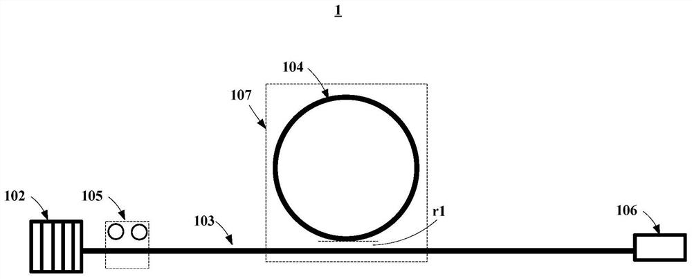
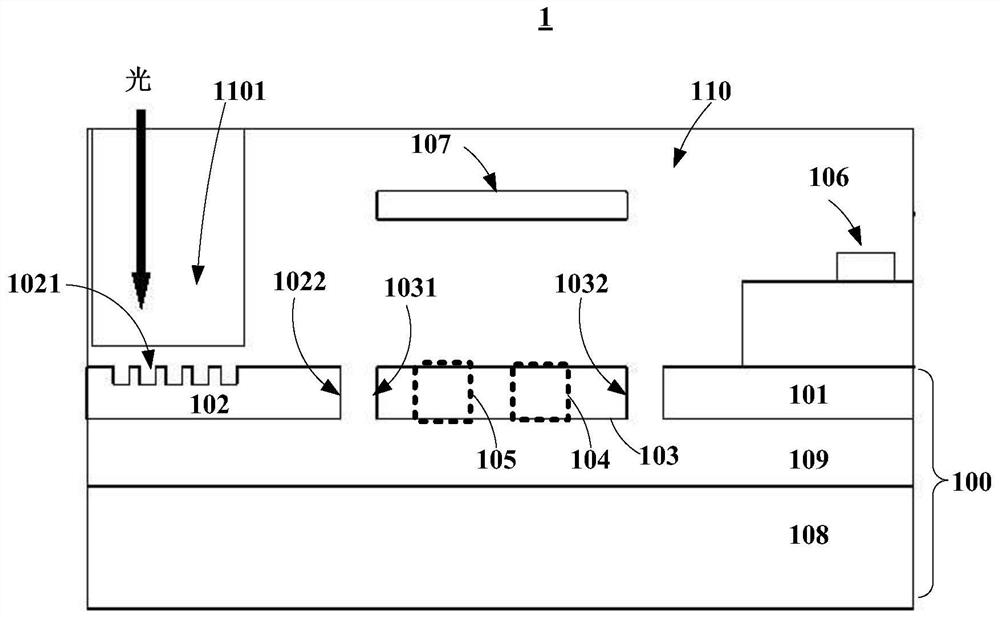
[0047] figure 1 is a schematic diagram of the on-chip waveguide loss measurement device in the first embodiment of the present application in the lateral direction, figure 2 It is a schematic diagram of the cross-section of the on-chip waveguide loss measuring device according to Embodiment 1 of the present application in the longitudinal direction.
[0048] Such as figure 1 and figure 2 As shown, the on-chip waveguide loss measurement device 1 includes: an optical coupler 102 , a linear waveguide 103 , a ring resonant cavity 104 , a polarization adjustment element 105 , a photodetector 106 and a heater 107 .
[0049] Such as figure 2 As shown, the optical coupler 102 is formed in the top silicon 101 of the silicon-on-insulator (SOI) substrate 100; the linear waveguide 103 and the ring resonant cavity 104 are formed in the top silicon 101, and the light incident end ...
Embodiment 2
[0081] Embodiment 2 provides a method for manufacturing an on-chip waveguide loss measuring device, which is used to manufacture the on-chip waveguide loss measuring device described in Embodiment 1.
[0082] Figure 5 is a schematic diagram of the manufacturing method of the on-chip waveguide loss measuring device of this embodiment. Such as Figure 5 As shown, in this embodiment, the manufacturing method may include:
[0083] Step 501, forming an optical coupler 102 in the top layer silicon 101 of a silicon-on-insulator (SOI) substrate 100;
[0084] Step 502, forming a linear waveguide cavity 103 and a ring resonant cavity 104 in the top-layer silicon 101, wherein the light incident end of the linear waveguide 103 is opposite to the light output end of the optical coupler in the lateral direction, and the The minimum distance between the ring resonant cavity 104 and the linear waveguide is the first distance;
[0085] Step 503, forming a polarization adjustment element 1...
PUM
 Abstract
Description
Claims
Application Information
 - R&D
- Intellectual Property
- Life Sciences
- Materials
- Tech Scout
- Unparalleled Data Quality
- Higher Quality Content
- 60% Fewer Hallucinations
Browse by: Latest US Patents, China's latest patents, Technical Efficacy Thesaurus, Application Domain, Technology Topic, Popular Technical Reports.
© 2025 PatSnap. All rights reserved.Legal|Privacy policy|Modern Slavery Act Transparency Statement|Sitemap|About US| Contact US: help@patsnap.com


